What's new
What's new

KO Lee B360 T&C table repair

smdubovsky

Hot Rolled
Joined
Apr 10, 2008
Location
MD
Looking to the folks who have run or repaired grinders for advice. I would normally ask the expert who originally did the work but he sadly is no longer with us:(

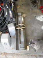
I have a KO Lee B360 tool and cutter grinder that had the ways reground and scraped a couple years back. I FINALLY got a little issue w/ the grit strip 'curtains' interfering out of the way and have gotten it back together. When I indicate in Z on the table it moves roughly 0.070"(!) along the table in the Y axis. I know that you regrind the top of a mag chuck when you re-mount it to the table. Im wondering more about regrinding the TABLE itself (technically, the carriage under the top swivel table.) Here is a similar pic of the carriage/top table I found on the web.

http://www.industrialsurplus.com/photos/049-499_4.jpg

Im running the indicator over the grounds ends of the carriage that the top table sits on (but indicating on the top table also shows the same error.) So the error is definitely in the carriage. The swivel top table contacts the lower table in three places. Both ends and the (off-center) 'island' that houses the swivel pin. It seems to me I must regrind these three points using the grinder itself. Being a little tool and cutter grinder, it has very little travel and can't do them all in one setup but can do each one individually. I can use my big camelback and surface plate to verify all three are reground to the same height.

The swivel table itself seems to mic parallel. All the problem is from the ways that were reground (the rear X way originally lost lube and took a beating - thus the rebuild.) So I'm not sure I would touch the swivel table itself as its very difficult to do it w/ the B360. If I get the carriage surfaces its sitting on level, then it should be level too. If I REALLY needed to touch the swivel top up, I'd take that to someone w/ a large enough grinder to do it proper in one setup.

Thoughts? 35thou of grinding (on average) is going to take a GOOD while even if they aren't big areas... The plates that indicate angle and such on the ends unbolt so I wont destroy them. Almost like it was designed to do what I think I have to do.
 
KO Lee T&C no parallel table

We still use one fitted out as a small cylindrical grinder. We had two problems over the years with table parallelism.

1. Table lifting out of the ways as workhead moves beyond the ways. Solved with a counterbalance bolted to the opposite end of the table.

2. Ways wore enough that way skirts were riding on the saddle. Solved by cutting back the skirt (the rear one)

.070" seems like a big number to correct for on such a small machine. Other causes? Male vee way tracking true to female way? Lead screw (if fitted) parallel to vee ways?
 
Do not exactly get what you are saying.. The machine movements should be having no wiggle.. Screws can have play because you measure and find zero going in one direction.. Table top flat and true because with having swing is rarely perfect except on a brand new machine.

"ways reground and scraped" good to take off table and check so see nothing out of wack"

.070 out of flat short way would not affect the majority of TC work. But yes you might set it on a surface grinder and top it . Couple hour job grinding perhaps or scrape it.. ( Think the under table is most hollow.)

* Might grind the center with its own spindle and scrape the ends?

Often the part or the part holder is tweaked in ignoring the table..Don’t know if I am addressing the right thing here...

To make it right might scrape the table out pads grind center and the table top (or under).. big job

*Is that a ball way table? We would grind the ball racks on cincinatti #2s one flat and one V so the amount of stock removal had to be calculated not just taken off.. you might check that as with wrong grinding the tilt would be of and an easy fix to restore. (yes we checked with Cincinnati first to find heat treat depth)

Quick check would be feeler check the gap between table and base.. proper check is take apart and measure.
 
Like Bruce said .070" is a ton to have just happened. It's a pretty simple assembly so I would pull the table and saddle off and look for dirt or something dragging under there. Something as simple as a bolt someone screwed in to replace a lost or old one and it went in to deep and lifted the saddle or table. Use your cell phone camera and take lots of pictures and get some plastic baggies and put the parts / bolts in them and write on the bag where the parts came from. Be patient and clean the parts as it comes apart and look for signs of wear.

When the old scraper finished did he install a green wearstrip material to fix the worn area? That's Turcite and it may have come loose and has moved and lifting the table. I would not grind the table top 3 pads as it has to be something else. The swivel plate sets on the table so lay it on your granite surface plate and check it with a surface gage it should be parallel to .001" or less. Take it apart before grinding anything. Do that and let us know what you find. Rich

PS: I am a Journeyman Machine Rebuilder.
 
More info is in order. Prior owner had the rear X way oiling fail as I had mentioned. Grit in the wells locked the oiling wheels and wore a flat on them so they didn't turn:( That caused a LOT of damage to the rear flat way. They kept using it doing rotary work so probably went unnoticed by them until far too late. There was at LEAST 70thou of wear. Probably more like 150+ in the center of the rear way. It was UGLY. Keith reground and rescraped everything so all the ways print well. He did install turcite (same as a big lathe he did for me prior.) Its not lifted. I've had it apart and back together MANY times now accounting for the movement of the rack and pinion, Y screw, etc. So the 070 tilt isn't coming from the ways. Its leftover from the damage before the repair. Wish I could just ask him why he didn't regrind the top (or tell me to do it.)

What stopped me from getting it all running again for a couple years was those curtains. Repairing the ways moved the X table down a lot and forward slightly. The curtains wouldn't fit back in and it was riding on them. I FINALLY found some time and got it up on my horiz mill to recut the grooves and also shortened the curtains. I didn't give him the grinding head just the base, saddle, table, and column (I remember he specifically asked for the column when I forgot to drop it off the first time so he could indicate on it to keep the Z square to the XY ways when he was grinding those.)

I'll still put the top table on the surface plate to check for bow. But I dont think thats the problem. Its not even installed when I'm indicating on the three top ground surfaces of the saddle.

So in a nutshell: I think I have a machine w/ as-new ways, rebuilt gearbox, new oiling parts from KOLee, etc. Just that the saddle/table top isn't level to the Y.

Thanks guys.

Edit: I see I didn't discuss the prior wear here. I must have been thinking of a conversation I had w/ some local machining friends. It was important info I left out. Sorry about that.
 
Don't think it would bowed but worth a check.. if you checked all and it runs good with ways in contact (for sure) so not held off by the rack or something so positive only the top is out of flat then topping or truing the three set positions would be the way to go .

Still not super important for use as each job is trued at doing but making it flat might make it like a new machine.

I have a KO Lee and never have checked the table top for flat short way.. also have never checked my #2 (Cincinnati) for flat. .070 might be about 1 degree with work head at 90* so flat might be better for ends work or the like. (or as it is just figure in the 1 * with more or less tilt)

Shame to be setting for a time would be good to set it up for end mill ends and drill points if nothing else.

Tilt and roll compound make the dials off on many jobs.. Often a scale set to the job and look across to a tall or horizontal target gets within a few thousandths close, then tickle grind for the last measure of off.
 
So he died before he finished it? Most pro's build the machine up so all 4 corners are the same height and would build from the bottom up and would indicate the 3 some what unworn pads while scraping the bottom. If you can't slide in a .0015" feeler gage in under the ways anywhere and as you crank the table over and it has lots of slop in the rack and pinion. I guess you could machine or grind those pads. I am just not excited about doing that because i feel there has to be something messed up under it that is not correct. Guessing with-out being there or seeing a picture is rough to give certain advice. Rich
 
Knowing the ways are fit. As Richard said a .0015 shim test and perhaps a blue-up to see ways are flat and touching along travel.

Simply grinding the table top and still having the three set pads off angle might make the top flat in the straight position (like a surface grinder) but where will it be when the table top is turned? The turning table is needed often as a means to away set the work head back for longer work.

Think it best to check the ways are square to moving. With knowing the ways are square I thing truing the pads will be needed, and then only a skim to the table..
 
Does your table saddle look similar to mine in the pictures below?
 

Attachments

  • DSCN1759.jpg
    DSCN1759.jpg
    90.6 KB · Views: 360
  • DSCN1761.jpg
    DSCN1761.jpg
    90 KB · Views: 434
  • DSCN1762.jpg
    DSCN1762.jpg
    93.7 KB · Views: 400
Personally, I would find the source of the machine geometry error before hacking away willy nilly on good machine parts. Assuming you have cleared all potential interferences and ruled out something silly like the rack climbing the spur gear, I would disassemble the machine again. Objectives are to check prior work and evaluate if bringing the table ways to "truth" uncovered another problem

Remove table and turn over referencing off the swivel table and indicate the ways. Assuming the ways had blued up properly, and indicate parallel, turn the assembly over referencing off the ways and indicate the table. Do the same on the swivel table alone and the main table reference pads.

Do the same thing on the saddle evaluating the parallelism between way systems. If they were not evaluated for fit, blue the ways too.

Finally, check the ways in the base.

You are looking for a .070" error. I believe it can be done with machined spacers, gage pins and balls. A surface plate isn't needed. A tooling plate, sheet of cold rolled or even a flat floor is good enough to find the problem(s). Once identified, you can decide on repair approach and desired precision.
 
Addendum

The parallelism (or lack thereof) is significant enough to find with a length of bar stock, some gage blocks or home made shims and pins or home made rounds and a level.
 
With hiving a roller table like 4GSR shows in post-10 if the blue up is good that would not change with adding the correct shim under the low side (s) of the roller holders as the whole geometry would move together, the flat and V. My Ko lee has actual flat oil-ways with no rollers.

Yes one could even take off from the bearing holder underside (s) to make table tighter to base or take off at taper after determine the exact amount by test shimming.
*I would grind a (two) flat shim to the taper needed.. perhaps .005 to .060 in the length if that proved what is needed if deciding to shim, but with that making the gap too wide I would take off the bottom.

Making the set pade near zero.(perhaps .003 or less short way and close to 0-0 long way error OK for TC work IMHO)
Yes 0-0 both ways would be the target.
Pads should be near zero long way and short so centers are 0-0 and table at swing is still flat.

Also run a strip of tape along table inside to give extra dust shielding. Just paint over and nobody will know it is there.

But yes consideration to what drive the table movement if rack or cable..Rack would need to fit well.
 
4GSR: It does NOT look like that. Mine has a one flat and one V way on both X and Y axis that contact full length - just like a lathe or a bridgeport. No bearings (roller or ball) anywhere.

I don't know how to say this more clearly: There is NOTHING wrong w/ the ways now. They print/blue fine. There are no gaps. There is nothing binding. The 070 is leftover from the extreme tilt wear PRIOR to it being rebuilt. The tilt of the table top has nothing to do w/ the current condition of the ways.

Seems he choose to leave the top of the X table tilted vs machining a TON out of the front V-way to bring it closer to level. Why not as it looks like all I have to do it regrind the three top X table pads and its good as new.

Imagine you are the factory w/ raw castings building the machine on the production line. When you grind and scrape in the X ways do you care about the 'level' of the yet unfinished top? I wouldn't think so. The order of operations I imagine with rough castings would be to bore Z for the column, grind & scrape the Y ways perpendicular to the Z, then grind and scrape the X perpendicular to the Y, and then machine the table top parallel to both X&Y so thats its perpendicular to the Z. The last step is unfinished.

I understand that *IF* there had been minimal damage originally, he could have ground/scraped the ways to keep the top of the table level. But w/ the level of damage, why constrain yourself to that? You'd have to remove a lot more material and its more work. If you just fix the ways so they are perpendicular and print(blue) correctly you can then proceed to the last step of (re)machining the top flat.

This seems really clear in my head but Im clearly having trouble communicating it.
 
You said: “Mine has a one flat and one V way on both X and Y axis that contact full length”
Same as my Ko Lee.. full length oil V and flat way under table.
With blue up good then I agree to grind the pads. Center one easy just grind with wheel head.. out board ones a little tricky with covering to keep grit out of works and perhaps weighted on same end (to off set the hang off the opposite end) to get the 2” or so travel with staying in the machine. With any problem grinding I would finish with scraping... but it should be easy grinding perhaps using a 46k or so wheel.

See that you will still have enough height so swing does not bump outer table sides or you will need to knock them down to clear.

Table needs to clear so it can be turned for doing end work in work head at 90*(or zero as how you look at it.)
You might turn table to 30* and the work head at 30* to get square end on a longer job.

.070 in the width of the table is about 1 degree off so if you left it you would just adjust that in to setting the work head protractor for end work.. it would not affect between centers or work head facing that way. Grinding the pads you want zero/zero for close between centers.
looks like the left side pad more tricky... you might make a bar to off set the wheel head to the left.
 
I have the B955 head which can have the spindle and pulleys flipped L to R to get over one far end of the table or the other if necessary. Since I have to swivel the column head mount anyway, I'm going to have to reset the Z height for the far pad at a minimum. The outer table sides are cast about 1/4" down on mine so I shouldn't have to touch them.

Looking at the specs again I only have ~4.5" of Y travel. The swivel pad diameter is within that but the table ends are a little over 6" deep. Going to be loads of fun...
 
Grinding in two sections is an easy task... just blue up first pass and the come to just witness then file flake in or scrape to match. With close a good honing stone and oil will take .0005 to .001 PDQ (pretty darn quick) End pads .0005 hgh would be good.
 
How can I say this...hmmmm...Different strokes for different folks. Have you ever set the table up on a plate and checked the bottom by setting 2 of the same sized V blocks and 2 equal sized jack screws? If the table is off .070 out of parallel I can see you grinding it, but if the bottom table is now parallel to the 3 pads, grinding them down in my opinion is the wrong way of doing it. I appreciate You didn't screw it up but the other guy did it for a short cut to save time. It's your machine and you can do it anyway you want to do it. I have never liked or recommended screwing up a perfectly good part to fix a screw up, which sounds like to me is happening now. Good luck. Rich

PS: He maybe planed on assembling it to find off how much he had to remove off the base ways to get it to indicate right. I do this sometimes when the error multiplies from a lower surface to a higher one. It might only be a few thousands. You could use feeler gauges to slide into the opposite side to estimate the amount you need to scrape off the bottom. This is only if the table is parallel. I believe you said it was. Rich
 
Last edited:
I think this thread would benefit from some pictures of the disassembled machine and or some sketches ,it seems the OP is confident in what is wrong and what needs to be done but on the other hand must have some doubt to be here in the first place.

I would be concerned that removing 70 thou could warp the casting so the ways would need re scraping anyway ,better then to re work the ways to bring the top back to parallel?


Back
Top