What's new
What's new

Possible to lock X on old Cin #2 ?

rabtrfld

Aluminum
Joined
Oct 11, 2016
Location
WI USA
CinCin2.jpg
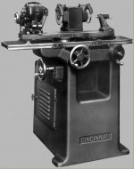
Is it possible to lock the X-axis on an old Cincinnatti #2 like this?
The handwheel (front left) is right at the operators hip and keeps getting nudged.
Besides, there's so much backlash you could jam the workholder into the wheel
like 0.05 by just leaning on it. This is not an actual picture of our machine but it
is close enough.

BTW is it normal for the direction of rotation to blast the dust up in the operator's face?
I tried reversing the motor :eek: and it worked great for a week, then the wheel came loose
because I forgot to check the clamping nut was right-hand threaded! Fortunately it did not
blast the wheel in the operator's face.

We actually don't have any NC machines in out plant, 15 "automatic" screw machines
from the 1960s and presses from the '50s including a 1948 model SN 005. Hard to find
manuals!

I take that back, we have an old EDM and one of the Bridgeports has an actual DRO!
 
Yes, it blast the dust up. I was surprised by that, but that is the way it was meant to work. If you take the spindly out and turn it around, then you can run it backwards and blast the dust down. This is the way I have been running my machine (I'm a hobbyist). I have plans on turning it around and blast the dust up into an exhaust system/filter. I think it will make cleaning the machine easier.

To lock the table, run the two adjustable stops up against the stop on the table. You can tighten it adjusting one screw once the two blocks have been brought together and tightened.

Vince
 
Thanks, but sorry, I guess I meant the Y-axis. I was comparing it to my lathe where the DRO calls X perpendicular to the spindle, Z is the spindle axis, and there is no Y.
On a mill X would be left-right and Y would be in-out. Anyway, it is the in-out distance from the wheel that needs locked. I see the left-right stop dogs, but we need that to move for our operation. Unfortunately the tolerance on our part is +-.0025" and every time a train goes by I have to rush out and check that they're not making scrap. Once I leaned on the machine by mistake while picking something off the floor, and scrapped about 20 parts just lining it up again.
 
I'm not sure how you can lock the Y-axis (other x-axis :-). I think you would have to do some drilling and taping to add something. You may be able to do something with magnets. Maybe a DRO would help tell you that it moved.

If you figure something out, please post a picture. I have thought that it might be nice to lock that axis, but never had a real need to.

Vince
 
I used to rebuild a lot of those years ago for Cummins and when you asked the question I started to think about it and Cummins guys made up a home-made one on some of their machines. I believe they had a flat bar stock about 1/4" think x 2" high and can't remmember where it was mounted. I think they blocked it out on the side and had a H shaped bracket it slid through that had a screw clamp that when tightened would lock the in/out. Sort of a C-clamp on bar-stock. Rich
 
I have run many #2s and simply leaning on the saddle would take a very hard push to move it in and out(cross)…Snug to the direction of the leads screw thread has always been enough to hold for no movement.. but long travel is easy to move and held fast with the table stops or the T-lock at the fast movement handles. I have taken off the front left handle (cross feed) on one machine that is facing the walk-way isle so it might not be bumped. Yes then its limited to the back-end handle only.

Changing the wheel nut direction by rotating the spindle is an easy job..the name face plate comes off the head stock casting so you can hold up the belt and turn the spindle 180*..tie up the belt with a piece of string or rope.. A five minuet job.. Turning the spindle may cause someone to over tighten the spindle end nut trying to take it off and turning the wrong way/ or put on the wrong mount(left or right) -> so best to paint red the spindle nut or etch LH.

Yes the spindle and wheel rotation goes up and down for different jobs so a right way is not possible on a TC grinder.

Richard's mentioned device seems simple enough to fab but I have never needed that.. green wheeling carbide was one of the higher pressure jobs.. but the snug up to direction of lead screw was enough to hold..Yes it would be a great idea for mounting an indicator holder as Cincy problem was not having a fine feed (.0001)at the feed handles. We had a few reamers that needed 50 millionths (half tenths) and so resorted to counting sparks to make good..

Working on the other side of the machine can solve some grit in the face problems. Yes newer machines may not have both-sides handles..

Often I down wheel most of the needed take-off,, then up wheel for the final skim tickle of a few thousandths.
*Get free down load of Cincy hand book to know how to remove and replace spindle...

Odd ball machine was a cincy #2 with a double long spindle at one end. (yes Cincy made). it was made that way to be a surface grinder..worked fine but using the .001 down feed was difficult to hole .0005. we used it to top broach inserts to flat with up taper,, then backed-off to just sharp.
On many broach inserts the last 3 teeth (or so) are made flat as finishers so that grind was done on a normal surface grinder(B&S or Thompson SG).
 
My 14X24 G&L #460 has table locks like R,K, described.Really thin like a piece of die rule with a pinch bolt/clamp to lock the axes.
My LeBlond #2 has a sliding post that the travel dogs can but against to lack the long travel and has lock bolt for the cross feed.Surprised that a Cinn T&C doesn't have table locks.
 
I can't visualise how this table lock looks. Could someone please post a photo or two? I'd like to add a table lock to my J&S 540 so am curious to see what these look like.
 
I added a cheapo DRO, took about 1 hour. Hard part was tapping #8s with lineman's pliers but it worked.


Back
Top