What's new
What's new

Right angle plate for surface grinder, how to prep?

ballen

Diamond
Joined
Sep 25, 2011
Location
Garbsen, Germany
I bought a surface grinder (150 x 450mm, chuck same size) this past summer and am learning to use it. One suggestion was to get a right-angle plate and make a grid of threaded holes on it, for holding parts. I just got this plate cheap, it's 80 x 100 x 100mm (3 x 4 x 4 inches). What grid spacing and thread are advisable? Should I mill off the diagonal ribs to get better clearance and to be able to use both faces? I have some precision 1/2/3 blocks that I can use to hold this to surface grind the faces.

attachment.php


attachment.php


attachment.php


Cheers,
Bruce
 
You might make a shoulder step above diagonal rib at one in-side and a V notch above the other inside but not mill out the rib, so a C clamp might hold round or square small part... A few bolt holes to hold a angle block to set a dresser on..square up all sides to perhaps 8 or 12 millionths" if you can... .0002 is common and OK.
Yes bolt hole decrease the accuracy because they can hold a grit or dirt that might fall on the chuck.

Angle bar perhaps 3/4 x 3/4 x 4" long (yes make metric size) with a counter bore so a socket head cap screw doe not stick out high on the side...one SHCS and a clamp is normal not two SHCS..
 
Please don't cut the ribs! I have at least a dozen angle plates, and although the ribs can get in the way... The ribbed plate are much stiffer and more accurate than the unribbed ones. When used in a mill, you can really tell the difference.
 
Make the shoulder step with an under cut corner so you might hold a sharp corner part, make it an exact size from the bottom so you might put the fixture on a plate and check a ground part with a jo-block stack. make also the width an exact size so you might micrometer measure and perhaps from the out long-side so a part measure might also be made from that side.

The two side squaring is better done with a V block so no need to chop the rigs fronm an angle plate.
 
Buck, I'll have to disagree on making anything an exact size here. If this piece gets used, no matter how carefully, it will still need to be reground at some point and then the exact size is out the window. More important to get parallelism and angles as close as possible. You can always mic it to check the plate or part. As others have said, do not remove the ribs. If this is for general occasional use the a regular pattern of hole will be fine. In a production shop they would likely be placed for particular parts and it might be used for a dozen different parts and look like Swiss cheese. For general use 1/4X20 or 6mm on 1 inch or 25 mm centers should do fine. Drill ,countersink, and tap your holes before grinding. Mill a step just above the ribs about 4mm deep. Let it rest a while. Good time to make some tiny toe clamps and angle clamps to use with it.
Remember that the effort to do this right will show in everything you use it for. Take your time and keep everything CLEAN! It may be a tedious, frustrating job but by the end of the day you will be a better grinder or the machine may be for sale:bawling::D.
The chuck should be in as near perfect shape as possible. Use coolant if possible or allow for frequent cooldowns.
To do a good job you will need a type 6 or 12 wheel. Use as soft a bond as possible to minimize heat and grind pressure. See how far off the back of the chuck you can go and make sure that the wheel will clear. With the 6 or 12 wheel mounted and dressed (remember that this wheel gets dressed on the face and periphery) place the plate face down indicate the bottom in X down near the chuck. Take very light cuts as this wheel will produce more pressure that the normal wheel. Grind to clean up. Clean everything and place the new surface down with the front of the plate facing the wheel. Indicate in X and grind to clean up. Next turn one end to the wheel, indicate the face in Z and grind to clean up. . Now with the regular wheel you can grind the top parallel to the bottom and the other end parallel. Place face down and indicate the step in X. grind to parallel with the face. With a cut off wheel grind a 45 degree slot at the intersection of the step and back. This area will be good for squaring small parts.
all clamping should be cushioned with brass or copper to protect the plate. Never the less it will have to be reground someday depending on useage and care.
 
To do a good job you will need a type 6 or 12 wheel.

The OP's grinder is a modern machine and looks/sounds to be in exceptional shape. I would want to know what the mfgr's spec was for squareness and parallelism as a minimum, before taking that approach. Miniscule alignment issues will yield hollow or non-square work though the grinder will grind flat with wheels dressed to the chuck. Some grinders won't clear the chuck in Z with a type 6, so the work would need raised on transfer blocks

I would use other shop set up tooling such as magnetic transfer blocks, square them if necessary, and use a type 1 wheel with the part squared to the chuck. Then shim the work including with crayon marks or temporary differential grind on one side to fine tune.

I have a transfer cube ground and then scraped; and use that for squaring other small work. A lot of times scraping is faster than grinding, for fine tuning smallish items, though then the OP needs granite knees & other equipment.

So the question is now moving toward: "Better to make the part square by rotating it to one plane of the surface grinder sequentially and using auxilliary fixturing; or better to use 2 "square" planes of the surface grinder, assume that they are, and that the 3rd plane is also square so the wheel does not grind hollow?

It's a good practical question.

smt
 
Last edited:
While I would not cut out the gussets inside the angle plate, I would mill the ends and outsides of the gussets parallel with the faces. This will allow more secure clamping of other parts to the face of the plate.

As far as grinding it square, I prefer the two angle plate approach. Either use your existing 1 2 3 blocks as an angle plate, or make another similar sized angle plate. Grind the plates alternately, each time checking and shimming to improve accuracy. 4 or 5 iterations should get you to the limits of your checking accuracy.

I also prefer 4 face angle plates. After you get the main faces of your plates square, then mount to grind one side perpendicular to both faces. This allows you to mount a workpiece to the angle plate and grind two faces perpendicular to the mounting face as well as perpendicular to each other.
 
Thanks everyone for the advice!

I'm just getting started on this. The only things I have that are square enough to get me close are a set of 6 ground 1-2-3 blocks. I have now ground one outer face of the angle plate flat and the next step is to set it up so that the 1-2-3 blocks hold the second face square to the first and then grind that. I'm going to do a 'rough grind' to get reasonable reference surfaces, then mill, drill, tap, chamfer, then do the final grind. I want to avoid scraping because the tapped holes will be a pain in the a**.

Part of the new things for me here is to set up a self-proving square on the surface plate.
 
Study this.

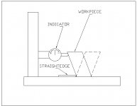
Gene, thanks, but this assumes that the part has two parallel edges. It won't work well here. The design I will copy uses to hardened pins ground to equal length, that are held horizontal to the surface plate in a jig. One pin is near the plate, the other pin is as high up as the top of the object. You touch off on your vertical surface (perpendicular to plate) then you rotate the jig 180 degrees around the vertical axis and touch off on the same pins, ON THE OPPOSITE SIDE. Provided that the pins are equal length, this proves vertical, or establishes out-of-vertical. Of course if there is simpler or better way that does not require purchasing precision tools, I'd like to hear about it! Cheers, Bruce
 
Gene, thanks, but this assumes that the part has two parallel edges. It won't work well here.

You can determine the "zero" square setting on the indicator by substituting any square or not square object with two parallel sides, such as your 1X2X3 blocks. It's always most accurate when the substitute object is the approximate size of the part that you are measuring.

Gene
 
I think of an angle plate used on a grinder to be hardened and ground tool steel rather than cast iron ,Thoughts?
 
I think of an angle plate used on a grinder to be hardened and ground tool steel rather than cast iron ,Thoughts?

Unless in my ignorance I grossly overestimate the problem, I think you're right: cast iron and any other soft/softish material would tend to get loaded with abrasive grit and become a very nice lapping plate.

Probably, it's not a true issue, if you don't use that angle plate anywhere near any surface plate and you're careful in varying your setup on the magnetic chuck.
Magnetic transfer blocks would indeed present even bigger issues in getting loaded with abrasive,

Beside for the above issue, I don't see anything else against using cast iron.

Paolo
 
Sable, spose its possible, but i have never really noticed it as a issue with anything i have done, then again, with a typical tool room grinder - jobs your cleaning everything off at every set-up any how. Its not like your plunking it down on grit, to hit the kinda pre-scion most grinding is all about you kinda have to work pretty clean and tidy.
 
QT Td : [Buck, I'll have to disagree on making anything an exact size here. If this piece gets used, no matter how carefully, it will still need to be reground]

Guess I much have to agree TD.. but I have a step angle plate with the to-plate dimension etched on the top.. When I re-grind it (not that often) I grind skim the top also and remark so I can go to the plate ..But that is not common so Bruce skip that for now.

Bruce does need a square checking device. A simple surface gauge with a round bump plate at the face...or the kind that holds a ball to bump the part along with a indicator..

Check a 123 block for dead parallel top and bottom. Then check with your square checker.. search to find the best 123 block 2 sides, Out of all the sides likely one set of sides will be near dead on....and mark it perhaps with gun bluing to know that will be your plate master for setting your surface gauge..

Srarrett design is good because you can put a ball or a round something in the front V for square checking off a plate.. with not having the V one can just grind in a V to a lower priced brand.
 
Last edited:
Good to know that anything set tall.. such as the part height more than the mag-held base is a tippy part and likely to set loose and fly off chuck. Perhaps grinding an angle plate would fall into this category.
With the angle plate set off chuck so the 123 blocks would mag most so taking their square, could make a tippy set up.
Trick here is to find another block to set on the go side of the set-up and clamp a bar to go from the extra block to the tippy set up and bump the tippy set-up high up.. very near the top edge where the grind forces are pushing most. Dead wheel over the part to be sure you will not crash bump the high spot then come in with feeds on the grind side until you find the parts highest place. Then watch sparks as you grind. Sparse sparks mean not huge grind pressure.. solid sparks may mean you are pushing too hard for a tippy set-up. (2 clamps or the bar resting on chuck because on clamp is often no help)
Much the same with block in blocks that are not square so hitting the part low is almost worthless for a tippy part..block must be square to the part, or bum block high on the part. Soft fixtures like cast iron and even CRS are good because the mag-hold better..Hard fixtures for close work are good because they stay good longer.

Fine wheels like a 60 or 80 are not rough in wheels..often a 36- or 46 grit is the safer choice.
 
If serious about using that angle for precision work, this is what I would do: mill a clean pad in the '12601' area; make a block, ~1"x2"x whatever the height is from the pad to the standing end of the "L"; drill/tap 2 holes [spaced 2"?] in the plate, and drill/counterbore the block for capscrews[~6mm?]. Now you can fasten the block to the plate and it will be at the same height as the "L" and even with the edge where the pad is. You may now grind the "L" and block parallel, flip and clean up one surface. If you have a known square angle plate you can use that to create the other surface square to the first; If not, then you may grind the other edge and side of the mounted block parallel. Check squareness carefully with a dial indicator and bar.
You may adjust the squareness by grinding a few tenths away all but a strip by one edge, then lay it on that surface and grind/cleanup. Flip and grind parallel. Takes time, cleanliness and patience, but you can get there.
JinNJ
 
QT:[What grid spacing and thread are advisable?]
You can always add more threaded holes so guess I would start with two, perhaps 1 1/4 down from top on the 100 x 100mm side and just inside the ribs...yes near 1 1/4 in a standard metric so 31/32mm... and a standard metric thread near 3/8-16... perhaps 10 mm.

Size is not so important for an angle plate.. all sides should be near dead square but one has plenty of chances to make it that way. The last .0001 is difficult so one may have to hand hone or lapping plate that last bit to near zero...and even then for close work one needs to check the part as it is held.

A V block is handy , one that can lay on its side so you might make a top flat and two sides flat, to a held part. Simple touch and take amount is often close enough to get perhaps +- .002 or so.

Odd trick with a V block is to make a collar like a lathe dog with having a long socket head cap screw as the holding screw.. You clamp it to the V block held part and set the screw head on a block with a jo block stack on top of the block.. Removing the stack allows a turn of the part to a very close amount..Yes you have to figure the part diameter and to the head set position..This is a way to turn the part for an index such as 2,4,6,20 or what ever you wish. A set of adjustable parallels can be handy for this set dog index. Agree it is not perfect index but close.
*Yes you might just buy a V notch lathe dog to use for this..
 
Last edited:


Back
Top