What's new
What's new

1 August 1915 ATW Ad

johnoder

Diamond
Joined
Jul 16, 2004
Location
Houston, TX USA
They were thinking towards super lathes even if they were not making them yet


1915Adsm.jpg


John
 
About the neatest looking "motor over head" design you'll find. Also, if you tire with watching the turnings fall just look straight ahead and watch for any sparking on the open 25hp commutator! :eek: My old American shaper has those same star shaped knobs. :cool:
 
In another doc ATW mentions they offered their lathes as lineshaft or direct motor drive. In the latter case, they used a geared drive. The power entry shaft was the same in either case, the difference being it was fitted with a flat belt sheave or a gear.

Regards,

Greg
 
i'm thinkin' standing in on the controls
during 945 lbs an hour clasifys the operators of these machine tools as the real men of the time
yup
nerves of steel
that's one of the fasinations with theses old machines
they bring many a ghost with them
sleepless nights over "the job coming up tomorrow"
not be because of the tolerances but
the sheer size and power involved with pulling that handle down and then hanging on while the iron flew.
nothing between you and that cutting tool but a little understanding
great pic john
 
Thanks WB


Here is another from the same booklet (Greg M. will be scanning the whole works and adding it to the ATW stuff)

The letter that is beside this photo in the booklet is dated 1911 and says no smaller (pilot) drill is used and that is but five hours work (the pile of chips). Wonder who made those silly flat-but-twisted drills?

I like the two-by-fours in the set up :D
1915AdBsm.jpg


John
 
I have a atw drill of that type in the corner of my shop. What is sort of weird in the photo is that the arm appears to extend well beyond the table. Notice that the drill head is no more than half way down the arm, but at the front of the table and coolent catcher.

Mine has a massive cast base with a coolent catcher around the edge which is perhaps 6-8" thick that covers the footprint of the arm (unless you swing the arm to the side.)

What I can't see in the photo is what even keeps the machine rightside up or holds the 'little' drilling table in place.
 
This pic looks considerably retouched to me- the men look real but the machine looks right out of an advertising brochure. Perhaps the draftsman took a fair bit of artistic license, and maybe thats where the odd-looking perspective came from.

Neat chips though...


Regards,

Greg
 
I like the idea of a crank that engages with the rack to move the tailstock along.
Not just an idea---but a necessity. I have a couple of these big lathes and I would estimte the tail stocks weight 500 lbs or so, and even with the ways well oiled---something you never forget to do after you get ahold of the crank--- sliding the tail stock by just grabbing in and pushing it down the bed as you would with a small lathe just isn't in the cards.

the bigger swing models had a gear reduction on the crank so you could crank them.
 
Ad pics were often re-touched to "clean up" the machine and show it clearly. Showing the machine dirty, with paint scratched up, and covered in chips wouldn't have fit the bill in those days, it would have been "bad advertising". In the pic it obviously was retouched.

As far as the perspective, it looks to me like the workpiece is a longish round part that is clamped to the side of the table about halfway along. That would make the position of the head about right.

BTW, when discussing hot chips and so forth, take a look at the overalls..... whoever designed overalls surely made them the right way to capture hot scratchy chips and funnel them down inside the overalls :eek:
 
There is a cartoon in "Bull of the Woods" entitled "Man's Inhumanity to Man". It depicts an old lathe hand leaning on the carriage of his lathe, asleep during a long hogging cut. The hot heavy chips are flying. The other guys on the shop floor are speculating whether a hot chip wil go down the guy's neck.

In another of the "Bull of the Woods" cartoons, two "collegiate" types show up on the shop floor, nattily dressed, reporting to the Bull for work. The Bull, knowing these two dudes are not machinists or shop hands, is assigning them to help shovel piles of "turnings" or chips into railroad cars. The Alliance Machine Works, where the Bull was boss, produced carloads of chips.

That old American Tool Works Engine Lathe and radial drill were taking quite the hogging cuts with probably nothing more than High Speed Steel.
As for the " 2 x4's" in the setup on the radial drill, this was nothing unusual. The "2 x 4's" were, in all likelihood, pieces of hardwood. I still setups on boring mills, vertical turret lathes, radial drills and milling machines made using hardwood blocking under the tail ends of the straps or dogs. Hardwood blocking does a great job in that type of application. I've used it a number of times myself.

Joe Michaels
 
John, Joe, and the Rest of You --

I'm curious what you guys call the pieces of wood or metal used to support the non-workpiece ends of those clamps, and for that matter, what do you call the clamps themselves?

Thirty years ago, my instructors and mentors mostly called them "heel blocks" and "straps", while an older English fellow insisted the blocks were properly called "packing".

There are few "gooseneck straps" (what I call 'em) where I work, but everybody else thinks they're "dog ears" or "puppy ears".

John
 
Here is an image of the 60 ATW drill extracted from the materials Greg's atw materials posted
at "atw.vannatta.com"


atwdrill.jpg


This particular drill from a 1911 catalog is very similar to mine except that mine has a 't-shaped'
table on the floor with coolent collector all the way around. --- the quick change box sits on the side of the machine instead of behind it as shown here.

I unforunately don't have the nice elevated table that mounts to the base --- so I have a fabricated table bolted to the T-slots out front
with a big shaper vise bolted to the table for the actual drilling.
 
RE: pile of chips.

It shouldn't have been too hard to get a pile of chips that size in a few hours. I just drilled a single hole with a 2 1/16 bit 5 inches deep and it makes a fair pile. A little jockying with the camera could make it look bigger and I did my drilling on a lathe so I was hand feeding, and rotating at a very conservative speed.
The ATW arm drill has plenty of power and a power feed. It will drill at any feed speed/rpm you want including plenty of choices that will melt the end of the bit off. (I've got some bits to prove it).

london10.jpg
 
Great pictures John.

I hope this is appropriate to ask since this thread seems to include a few fellas who know their way around a radial... (not trying to hijack the topic) We just aquired/traded for a "Cincinnatti-Bickford" 11" x 60" drill, and have not been able to locate a source for parts or manuals. Any tips? There are a few minor switches and brackets that were callously removed/knocked off during transport to our shop, and they have been mangled beyond identification. Any help would be appreciated.

Christopher
 
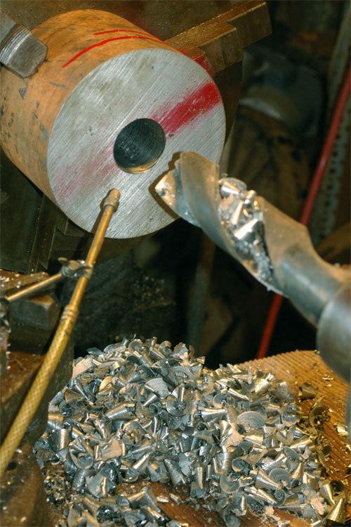
The flat, but twisted drill was a common practice in the war production era. A piece of HSS would be forged, twisted, and then cast into an ordinary steel shank. This was done to preserve precious HSS. It was also not unusual to find reamers with brazed tips of HSS, and a plain steel shank in sizes as small as 1/2 “, much the same as we do with carbide these days. I have several of both at work. The drills of this type were much more popular in the larger sizes; I have some up to about 3 ¼. I do recall seeing some as small as 1 ½ .

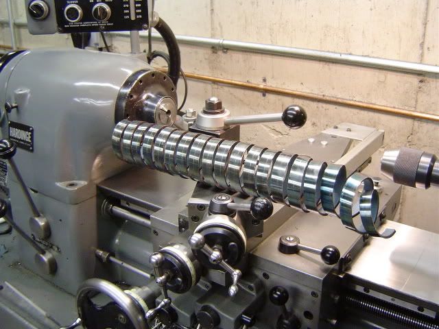
The old lathe pictured is similar to some that I have run, and it is always surprising to see the kind of cut they can take. The older machines are geared to what would be considered ultra slow spindle speeds compared to a modern machine. This was done to take full advantage of the hogging capability of HSS, and I suppose originally plain tool steels. In other words a HSS tool bit won’t take a 0.06 cut at 200 FPM with any feed rate for very long, but it will take a 0.75 cut at 80 FPM with a 0.090 feed all day long if the machine has the power.

I learned to rough like this when I started out from a real old school fellow. There are a few tricks. The first of which is to use a square ended tool bit, and cut with the end of it. The tool holder of the Armstrong type using a regular tool post is set as close to the axis of the shaft as possible. This allows the thrust of the cut to be in line with the holder. If you try to cut like this with a holder perpendicular to the shaft and a side cutting tool the holder will twist in the post every time. The other reason for using a square ended tool is that they are easy to sharpen with minimal grinding. The depth of cut should be all of the tool bit width, minus a touch. The speed is right when the chip is a deep blue/purple color. Then you just keep stepping up the feed until the machine just about stalls, or the tool breaks, then back it off a little. The idea is to maximize the depth of cut, because the tool life is affected minimally by it. You control the amount of power required with the feed. It is better to take 2X the cut at ½ the feed, as you will have to stop cutting less to set another cut. It is not a good idea to have your face over the top of the tool; as if it breaks it will hit the ceiling. Once you get the cut going right, you get over to the grinder and sharpen another tool for the next cut. You need to stick the tool bit out of the holder far enough that the chip clears the tool holder. If you do not clear the chip it will quickly wear a slot in the holder, eventually ruining it. It also is surprising at how dull the tool can get and still cut. Sometimes the tool would have a 1/16 radius on the cutting edge at the end of a long pass that was still cutting fine.

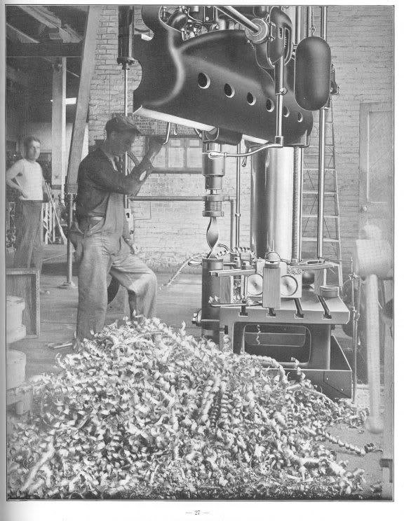
The chips are the fun part. First of all they are plenty hot and heavy enough to burn a hole in the sole of your boot. They are also sharp and, more often than not, very ragged on the edges, which make them ideal for snagging clothing and skin. Because the chips are so thick, and must not be allowed to break on the edge of the holder, they get pretty long unless you break them manually. On a smaller lathe you simply whack the curl with the back of your 12” crescent wrench, breaking them every 6-12 inches or so. On a big lathe you let the chip run to the floor, and break it with a 20 lb sledge by dropping it vertically from a foot of the ground every 3 feet. This length makes them easy to pick up after they have cooled of some. With this slow and heavy hogging you end up with a fair amount of time on your hands. Time to break the shop record for length. The chip is turning as it lengthens, so it you want a long one, you must set weights on the floor to keep it from rolling and eventually binding and breaking. I had a 40 footer once, but have heard stories about running a chip all the way down the street!

I don’t get to cut like that much anymore, with modern carbides being the norm these days. Once in a while the opportunity arises where it is called for. The chip in the picture came off of a Niles 56 x 360 lathe, in which we were roughing a shaft for an old hydro-electric plant. The lathe in the picture is obviously not where the chip came from, and unfortunately I don’t have an “in action “ pic, but it gives an idea of scale. The shaft was 10” dia. 4140HT, about 20’ long. There was a considerable amount of material to come off, and that was the only lathe it would fit into. The machine was probably built in the 30’s, so that means no speed for carbide. It is fun to listen to the gearing in the headstock tighten up and groan as the tool starts to cut.

BIGCHIP002.jpg


Back
Top