What's new
What's new

American Tool Works 18" Lathe - Evaluation

Adair Orr

Aluminum
Joined
Apr 11, 2006
Location
Seattle
I'm currently sitting on two big lathes. Both are projects and both are probably beyond my abilities or at least time available to get running.

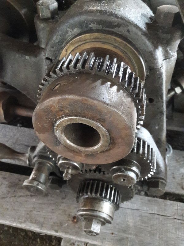
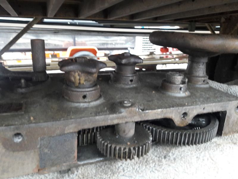
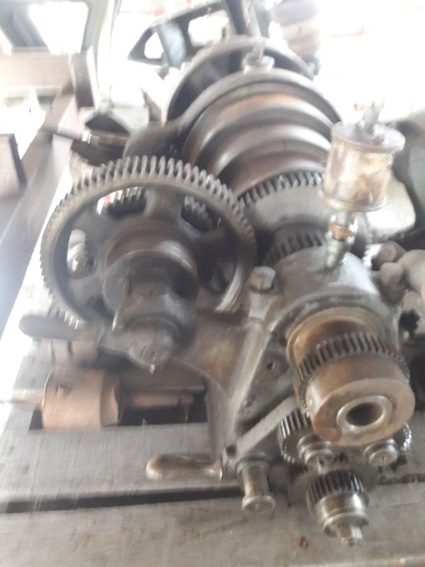
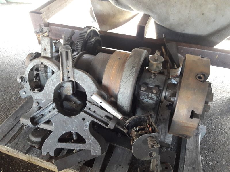
I just came across this ATW lathe. It is probably a better candidate for my shop. Most things appear to be intact. It has a double back gear, a gearbox, and an over-arm motor mount for the countershaft. Known problems are as follows:

1. Tailstock spindle is stuck. I can soak it and get it free.
2. There are few chipped gear teeth. One on the larger of the two back gears.
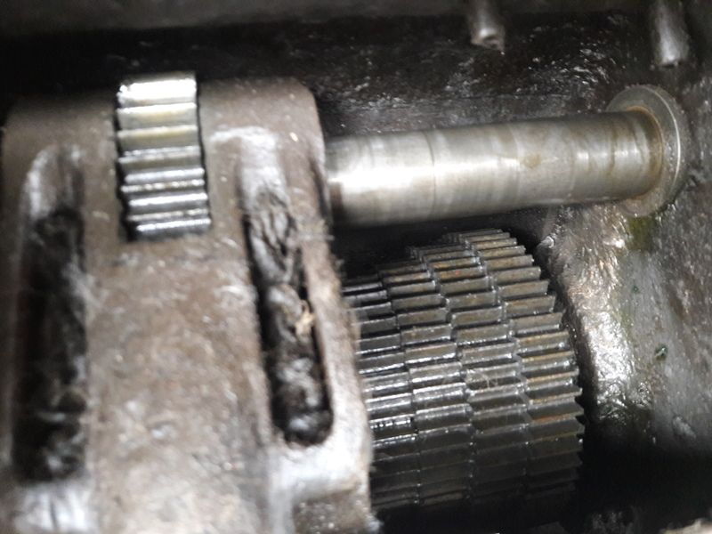
3. There is a bit of play in the index lever of the gearbox. I imagine this just needs a new bushing. See attached video.
4. One of the two knobs on the apron has been brazed back together. I don't know what that knob does so I'm not sure what caused the break.
5. I think these lathes had a cover over the gears on the back of the headstock. If so, it is missing. I can fabricate one.
6. The lathe is in parts so it is hard to assess the whole machine.

Other than that, it looks that gear teeth are not badly worn, the feed screw is in good shape.

The owner intended to sell for industrial furnishings. I think I may offer my 20" Leblond gap bed lathe in trade. He can sell the legs and make more money off of scrap since the lathe is much heavier. I hate to send any of these beasts to such a fate, but the gap bed is way too much lathe for me.


John,

Thanks for the reply. I will practice pinning, brazing, and filing new teeth on old change gears that I have in the shop.

As far as the cross feed clutch knob, I still can't figure out how it would have failed the way it did. Impact?

I hope this lathe is the addition I've been waiting for. I hate to give up on the other two machines. Right now I just want to have one running.

-Adair
 
Maybe it was stuck good (they do that) and they were a little over enthusiastic about knocking it loose:D


John,

Thanks for the reply. I will practice pinning, brazing, and filing new teeth on old change gears that I have in the shop.

As far as the cross feed clutch knob, I still can't figure out how it would have failed the way it did. Impact?

I hope this lathe is the addition I've been waiting for. I hate to give up on the other two machines. Right now I just want to have one running.

-Adair
 
The gear on the spindle w/ chipped teeth can be removed and replaced, the teeth are not cut into the spindle. These machines came with a thread dial, would be good to see if thats present. As John mentioned, theres not much to those star wheel knobs, check to see if the knob operates freely ie not seized due to bent actuating shaft.

There should be cast iron covers for all the quadarant geartrain, also missing the quickchange box placard- the covers are generally cosmetic items but the quickchange placard is pretty important if you're going for threading and reasonably precise selection of feed rate.

The spindle bearings are tolerant of wear but they can get pretty sloppy- drop oilers still in place is a good sign. Its hard to get a reasonable setup for measuring spindle play with the headstock off- if the wear isn't really bad you can adjust the shim packs between the spindle bearing cap halves and reduce clearance but that only goes so far.
 
Greg,

Thanks for the suggestions.

The thread dial is present. The star knob is free and locks the gears as it should, I believe.

I'm sad about the missing quadrant cover. Aesthetically and safety-wise, that is a nice feature.

The quickchange gearbox brass plackard is in a box with loose parts. I think every fastener is there.

I won't know about the spindle wear as you mentioned. That is a risk I will have to take. If the wear on the rest of the lathe is indicative, I feel OK. There seems to be no noticeable backlash and the cross feed is smooth across its' length.

-Adair
 
The condition of the cross-slide screw and nut is a good sign. Often they take a beating on high-mileage machines, original handles also promising. ATW used standard dimension 14.5 deg gears so are reasonably easy to replace if repair is not on the table.

The spindle bearings are fairly complex, there is a gallery packed with wicking surrounding the bearing shell, there are openings at the top and bottom of the shell for oil to feed onto the journal. The idea was the gallery would retain quite a lot of oil so the bearings would have at least some lubrication even if indifferently maintained. That wicking may be packed off at this point, possibly filled with wax if old-school motor oil was used. If you pull the bearing caps you can get at the packing material which can be picked out of the gallery and replaced with felt.

Similar wick material can be seen in the quickchange shifter, either side of the drive gear. The idea is the shifter is positioned below oil points which drip right into the wick material, lubricating the next gear (and its mating cone gear) in the train, the packing material providing longer-term lubrication; same kind of idea.

Bonus points for getting two steady rests, the larger one looks OEM, smaller one does not.

Open holes on the apron control bearing assemblies can profitably be filled with gits oilers to keep things cleaner.


Good luck!
 
Greg,

Two more questions for you since you've been so helpful:

The first photo after the video I posted, the one of the quadrant gear train, there is a cylinder on the lower left that pulls out a couple inches and returns. Could you tell me what that is?

Also, is there a name for this type of ATW lathe? If I go ahead with this I'd like to get photos of the gear cover so that I can fabricate something close.

-Adair
 
The lathe is a pre 1927 High Duty, that series was produced from approx 1911 until the early 1940's, quite a few design changes accumulating over that time. The final revs of the design were like mini-Pacemakers, not in the same class of machine but sharing some of the design elements. I think yours is likely fairly early because the carriage feed pinion looks to be fixed, later revs of the design made the carriage drive pinion so it could be withdrawn from the rack.


I have a number of ATW docs which includes a fair number of product brochures for the High Duty machines

http://pounceatron.dreamhosters.com/docs/index.html

I had a 1912 14" that I gave away, and currently use a 1936 12" High Duty in the garage, some pics in the page here

http://pounceatron.dreamhosters.com/


That round knob pulls a spring-loaded pin that holds the quadrant in forward or reverse position so that the locking nut can be tightened with the correct mesh. Reversing the geartrain tends to only be needed if you are cutting left-hand threads, the apron has a feed reverse gear so generally the quadrant is left in "forward" position.

Note that all the quadrant gears including the tumble gears run on journals drilled thru the end where a right-angle git oiler should be installed- so you can inject oil down the center of the journal and it feeds out onto the journal surface.

Bourn & Koch have a serial # list for the High Duty machines but no parts. They do sell a general set of drawings of the various High Duty sizes and options, but they are not prints- no dimensions- so not suited for making parts.

Regards,

Greg
 
Looks very much like my first lathe, still have it (not used due to need of spindle bearings) It has the leadscrew in between the bed ways, what years did ATW do that? The newest patent date on it is 1917 IIRC.
 
I think John is right, born out to some extent by examples of the machines on ebay etc. There was some crossover between the previous "New American" model lathe with the leadscrew between the ways and the next design being the High Duty. A few years ago an example of an early High Duty headstock was mountdon a New American design bed surfaced on ebay. The New American design is not well documented in the product literature, but generally extended from the late 1890's till approx 1911. In the early 1890's there was another ATW design- no gearbox etc I think likely designed when Mr Lodge was involved with the company.
 
"Rebuilding a machine like this is like eating an elephant: "One bite at a time". Good Luck, and Have Fun. Regards, Clark"

Clark,

Thanks for the warning. I've now moved 2 big lathes in and out of my little shop, getting neither of them running. I hope this ATW is one I can tinker with and learn how to manage a big flat belt machine. I'm not worried about high precision for my applications. I guess the worst that can happen is I move this lathe in and out again and regain a large chunk of shop floor space for tools that I make good use of.

-Adair
 
I did end up trading for this lathe. I've been putting it back together. Outside of a couple extra taper pins and one machine screw, it appears that all parts are accounted for.

I have a question about the carriage lock:

I'm getting ready to put the apron back on the carriage. There was one long guide with adjustment on the rear of the carriage. On the front there are two independent guides at the head and tail end of the apron. The one at the headstock end snuggs up nicely and allows the carriage to slide. I have a question about the tailstock end one which is integral to the carriage lock. There are two machine screws that secure it at the ends, and the carriage lock bolt in the middle. I assumed the machine screws are intended to snug up with enough tolerance to allow it to slide, and the carriage lock bolt "deflects" the guide thereby clamping the carriage to the ways. Is that correct?

When I snug down the machine screws on the end, the carriage will not slide. Do I need to scrape the mating surface until the carriage can move? Shim the ends?
Carriage lock plate.jpgCarriage lock.jpg20180325_143836.jpg
 
Close fits on the "hold downs" are only possible if the bed has no wear. Say near the chuck it was worn .015" vertical and not at all at the other end. To get it (the assembled carriage) to go all the way to the right, the hold downs would have to be at least.015" loose at the chuck end. :)

I did end up trading for this lathe. I've been putting it back together. Outside of a couple extra taper pins and one machine screw, it appears that all parts are accounted for.

I have a question about the carriage lock:

I'm getting ready to put the apron back on the carriage. There was one long guide with adjustment on the rear of the carriage. On the front there are two independent guides at the head and tail end of the apron. The one at the headstock end snuggs up nicely and allows the carriage to slide. I have a question about the tailstock end one which is integral to the carriage lock. There are two machine screws that secure it at the ends, and the carriage lock bolt in the middle. I assumed the machine screws are intended to snug up with enough tolerance to allow it to slide, and the carriage lock bolt "deflects" the guide thereby clamping the carriage to the ways. Is that correct?

When I snug down the machine screws on the end, the carriage will not slide. Do I need to scrape the mating surface until the carriage can move? Shim the ends?
View attachment 224741View attachment 224740View attachment 224742
 
John, Thank you for the explanation. I didn't consider the wear, a factor that at this point remains unknown, though there is no pronounced ridge in the ways.

After much web searching, I realize my terminology is off. The components I am describing are the gibs on the saddle. Maybe these are accessible even after fitting the apron. That would be ideal.

The rear gib has grub screws. It seems to fit very nicely with no noticeable play. As I mentioned, the "left front" or headstock end gib also fits snug while allowing movement of the saddle. It seems to only be the gib that is part of the carriage lock that is too tight.

-Adair


Back
Top