What's new
What's new

Bramah and Maudslay

Asquith

Diamond
Joined
Mar 3, 2005
Location
Somerset, UK


Joseph Bramah was responsible for some important developments in the late 18th/early 19th centuries. These included the hydraulic press, a large wood planing (milling) machine, high security locks, and beer pumps. I want to concentrate on his role in industrial machine tools.

In 1784 Bramah patented a lock which was extremely difficult to pick. He was responding to a dramatic increase in theft and burglary. His locks needed many components which had to be fairly accurately made.

In 1789 he took on a young Henry Maudslay to assist in mechanizing the various stages of manufacture. It is noted that large-scale production of the locks began the year after his arrival. Maudslay left Bramah in 1797.

Some of the lock-making machines, jigs, etc have been preserved. They are interesting as examples of late 18th century production machinery. We will never know the relative contribution of either Bramah or Maudslay.

In the context of the 'machine tool revolution', the machines themselves could not have had much direct influence at the time, as they worked in secrecy. However, we do know that Maudslay went on to have an enormous influence, partly because his own business was by no means secretive, his machines being very much in the public eye, and also because the Maudslay 'nursery' gave rise to important developments in the machine tool revolution of the first half of the 19th century, through Whitworth, Richard Roberts, Nasmyth, Muir, David Napier, Francis Lewis, and others. They were some of the most inventive and ambitious engineers of their time, and they didn't pitch up at Maudslay's by mere chance.

After leaving Bramah and before the arrival of those eminent pupils, Maudslay made machines which represented a major advance in engineering production – Marc Brunel's blockmaking production line at Portsmouth Dockyard.

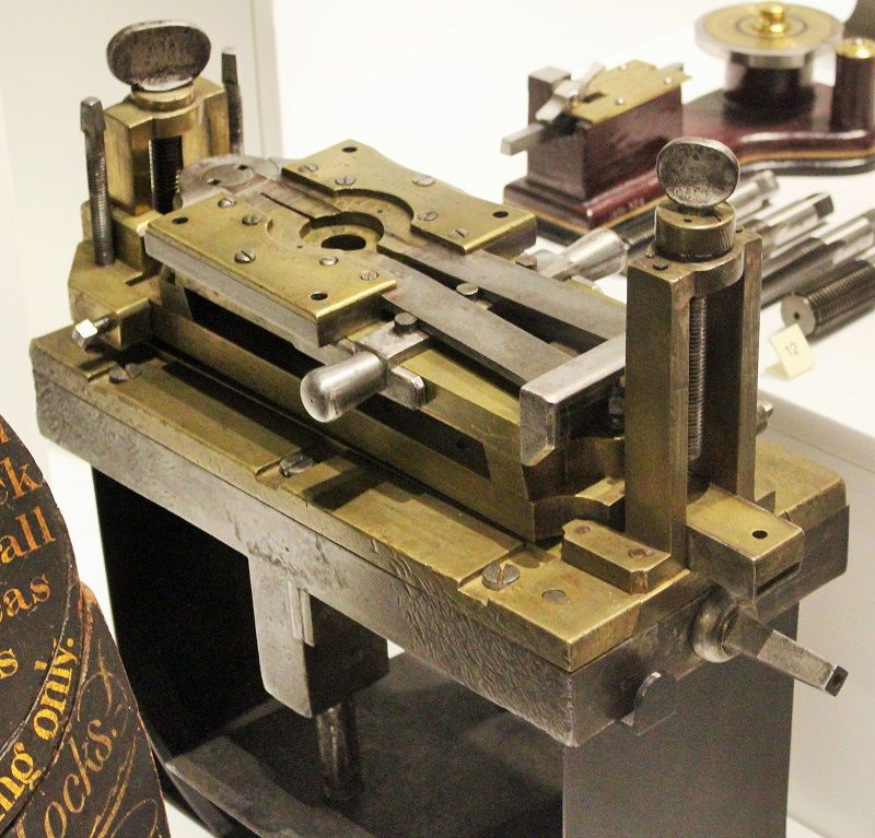
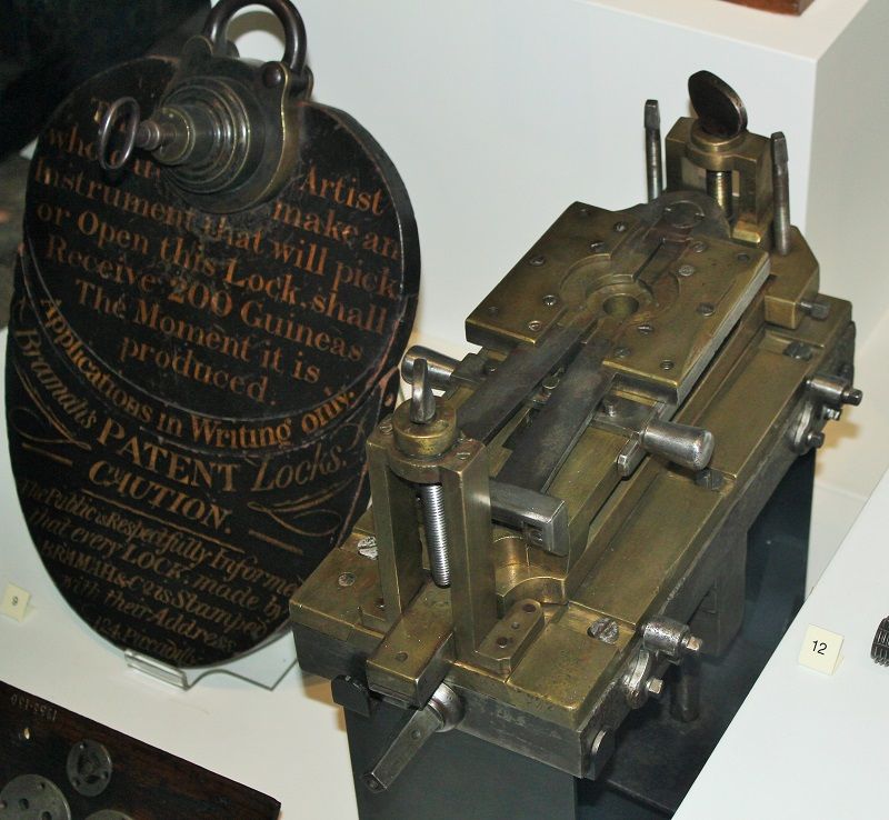
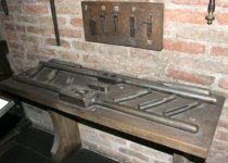
I'm going to return to the blockmaking machinery later. I will also offer some information on the lock-making machinery. But first I'll focus on the item in the photos above, displayed at the London Science Museum.

It's title – Quick Grip Vice – underplays its role. It might be better described as part of a milling machine.

The cylindrical component is clamped in the recess, the jaws being tightened by pulling on the two steel or iron handles. A better photo here:-

http://cache4.asset-cache.net/gc/90770796-vice-made-by-joseph-bramah-to-be-used-gettyimages.jpg?v=1&c=IWSAsset&k=2&d=X7WJLa88Cweo9HktRLaNXmKi%2FnDEcxrJPlLUgXBvQGsWPWQFbvu%2FX2RoP5ZrqYtzXv1j%2BGAhGuqV7An0RPPqpZhtSM%2F0lgwE2GbC6sjlqA4%3D

The vice can be tilted, being pivoted at the far end. The pivots are attached to a bracket which can be raised vertically in guides. At the near end, a handle was presumably attached, and the vertical screw perhaps served to limit the vertical movement. Below there, we are on more familiar territory, with a square-ended leadscrew for a cross slide guided by dovetails. You can just see the angles of the dovetailed guides. These brass guides are screwed to a cast iron T-shaped baseplate. This was bolted to the bed of a lathe. The vertical leg of the baseplate has packers attached, no doubt to locate it in the jaws of the bed.

Rotating cutters, which we would nowadays call burrs or rotary files, were mounted on a mandrel running between centres. Here’s a photo:-

http://cache2.asset-cache.net/gc/90770763-made-by-joseph-bramah-bramah-made-numerous-gettyimages.jpg?v=1&c=IWSAsset&k=2&d=X7WJLa88Cweo9HktRLaNXhi9hB2bFr5c4LfEVhLO0ZTiCpp7FmrNFSz1kb%2FsQwRtER65E1jh3TUnknxhqSPZStKigXJE6M3ryjGhdFTS6I8%3D

What we have, then, is a sort of horizontal milling machine. I don't know what it was milling. One source says that the vice held 'the caps of the locks while the bolt run was slotted out' ('Joseph Bramah' by Ian McNeil, 1968). Presumably the depth of cut was set by the vertical screws, and the workpiece fed under the cutter by the cross-slide handle. I don't know how you'd ensure that the vice and workpiece were truly horizontal having made a height adjustment. That's one of the problems with these Bramah items: despite their apparent importance, they don't seem to have been addressed in depth.

More to follow.
 
Last edited:
JD Bramah lock09.jpgJD Bramah lock06.jpgJD Bramah lock.jpgJD Bramah lock05.jpg


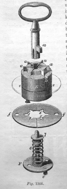
The extracts are from The Cyclopaedia of Useful Arts, 1854. I can attach the full text if anyone's interested.

The key has a number of axial slots of various depths which press down on a series of thin plates aa. This action allows the key to be turned by lining up slots (fig 1367) in the thin plates with Disc ff in Fig 1366.

The thin plates were housed in radial slots in the brass cylinder E. Making these slots posed an obvious production challenge to the men in frock coats and three-cornered hats in the 1780s. They were cut by this special machine:-

http://cache2.asset-cache.net/gc/90777823-machine-for-cutting-slots-in-barrels-of-locks-gettyimages.jpg?v=1&c=IWSAsset&k=2&d=X7WJLa88Cweo9HktRLaNXiZbNvBcpbDMDucvV8R7wIX6AcVQaJV%2BULUzrUf59QvCQ82sL19oMLOMpiP6yB50ZA%2BHcNRIenWhaDSLVnfwYGY%3D

In essence it used a reciprocating saw to cut radial slots in the cylinder, which was indexed round on the completion of each cut. The saw was fixed in a frame moved back and forth by a hand-operated lever. The frame was guided by having Vee-shaped edges which slid in guides.

The indexing head which held the workpiece was raised against the saw blade using the lever which disappears off the bottom of the photo. The handle to the left of that secures a lever which holds a guide for the saw blade. The indexing head allowed for a variety of slot numbers, from 4 to 18, I think.

The small print: The lock underwent various changes in its long production run, and I don’t know to what extent the lock shown in the above pictures relates to date of the machines discussed here. I don't think there's any doubt that the machines are from Maudslay's time there, although there obviously might have been some alterations. We see for example that there are some unused attachments on the slot-cutting machine.

More to come.
 
Another machine from the Maudslay period has been preserved. It's quite a simple thing, used for winding the small coil springs for the locks. The point of interest is that it can be compared with a screwcutting lathe. It produced springs of different pitches using a carriage in dovetail guides, driven by a leadscrew connected to the winding spindle by change gears:-

[url]http://cache2.asset-cache.net/gc/90742054-joseph-bramah-inventor-of-the-hydraulic-press-gettyimages.jpg?v=1&c=IWSAsset&k=2&d=X7WJLa88Cweo9HktRLaNXtbGE8xG%2FLhOOvWcbWQMy2vWbPgGo0njNdPgeV5Tf95R7gsM84w0lAkt0RpBuBBAD6Dcyg7cZ%2BjMWq89U50Tg%2FA%3D[/URL]

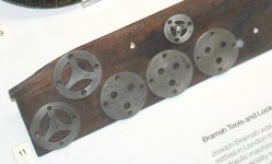
Also on display at the Science Museum, without any explanation, are these templates:-
JD Bramah lock07.jpg

Online photos show that these have spigots corresponding to the keys:-

http://cache3.asset-cache.net/gc/90770786-templates-used-for-the-drilling-of-bramah-gettyimages.jpg?v=1&c=IWSAsset&k=2&d=X7WJLa88Cweo9HktRLaNXs%2FZBCBm%2BMfFvq0MzzM%2FWBsSEJokqe%2FFltotEGHGQDl3Jnmz%2B51vpUnFyVCFvmTe3Y1CKHSfXZRYzGP1Ug2l8Oc%3D

http://cache1.asset-cache.net/gc/90770784-templates-used-for-the-drilling-of-bramah-gettyimages.jpg?v=1&c=IWSAsset&k=2&d=X7WJLa88Cweo9HktRLaNXiMwb5TeK13MaZmAw86OgOhvY5Z3b1XV7eg3alMPXn%2B6CEyBfRji1gjqLQxeOBj1HuHEzbmtKCAdKprfWNjMDhE%3D

Just one other machine is known to have survived, but I don't know its whereabouts. There's a photo of it in Joseph Bramah by Ian McNeil. He credits the photo to J. B. S. Gabriel. He was a bigwig in Churchill Machine Tools and in Cincinnati UK. The machine is described as a Nibbling Machine, used for cutting the critical slots in the end of the key. The photo shows a machine with a belt-driven headstock. At right angles to this is what appears to be an indexing head mounted on V-ways. There is also a dovetailed cross slide which has no obvious connection with the rest. There's a big lever and a large tension spring. That's about all I can say, other than the fact that it's all metal. Of course, it might have been from a later era. Perhaps that's why the Science Museum didn't take it into its collection.

In 1849 the eminent John Farey, writing of the machines constructed for Bramah by Maudslay, recorded that '...the notches in the keys, and in the steel sliders, were cut by other machines, which had micrometer screws so as to ensure that the notches in each key should tally with the unlocking notches of the sliders..’ (quoted in various sources, including 'A History of Technology, Vol IV,' Oxford, 1958).
 
Last edited:
Thank you for this post and the time it took you. I have seen these objects and never quite grasped how they all work. I now have a much better idea but am still trying to completely comprehend the lock mechanism itself.

The funny part about this is today I was working on a design for new type of miniature lock. It is a challenge when you add the scaled down component, it becomes like a gorilla trying to work the lock on a delicate tea caddy. Hence it has to have some strong internal parts.

Thanks again!
 
Thanks, Bill. It's nice to see someone other than me adding to my threads!

I was going to add extra images of the description of the lock from my copy of the Cyclopaedia, but Jim Christie has pointed out that it's available on line, so it may be easier to read it there (starts near end of page 197):-

Internet Archive: Error

Description and high resolution photos of a modern Bramah lock here:-

http://www.crypto.com/photos/misc/bramah/

Note that the sliders have more notches than required. This is because one of Bramah's employees, William Russell, came up with the idea of adding false notches, to make the burglar's job more difficult.
 
Thanks for the post Asquith.
Having scratch made (can't buy blanks!) several keys for early Bramah locks (museum items) I can attest to the fine workmanship of these locks..
Mark
 
Locks to Blocks

1 Portsmouth mortising machine

JD Pmouth blockmaking02.jpg 2

Finally: In post #3 I quoted from an article about Bramah and Maudslay in the Oxford History of Technology. The author of its chapter on machine tools was K. R. Gilbert. He was Keeper of the Department of Mechanical and Civil Engineering at the Science Museum. He wrote a booklet called The Portsmouth Blockmaking Machinery. Henry Maudslay’s precise role in the design of the machinery is not known, but Gilbert examined the evidence and gave the credit for conceiving, designing, and putting the machinery into operation is due to Marc Brunel.

However, I think that the basis of some of Mr. Gilbert’s arguments is open to different interpretation, and I suspect that Maudslay does deserve a great deal of credit for the detail design.

Certainly the 'architectural' design of the machine frames points to Marc Brunel. However, for all M. Brunel's genius, would he have the depth of experience needed to specify every aspect of the practical construction methods of the machines? Maudslay, on the other hand, was well-placed to know how best to design the details so that they could actually be forged, filed, machined, and assembled. Obviously this by no means makes a convincing case for claiming design input from Maudslay, but an aspect of the design has struck me as worthy of consideration.

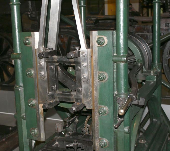
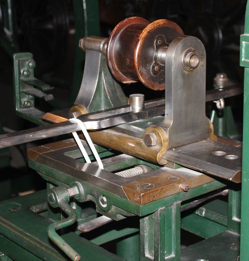
Photos 1 & 2 show one of the mortising machines from Portsmouth, displayed at the Science Museum. (This, by the way, was surely the inspiration for Richard Roberts’s 1835 slotting machine). I was struck by the resemblance between the method of guiding the tool holder on the mortising machine – a pair of opposing vees, whose two guides are each secured by four screws - and the saw holder on the Bramah machine:-

http://cache2.asset-cache.net/gc/90777823-machine-for-cutting-slots-in-barrels-of-locks-gettyimages.jpg?v=1&c=IWSAsset&k=2&d=X7WJLa88Cweo9HktRLaNXiZbNvBcpbDMDucvV8R7wIX6AcVQaJV%2BULUzrUf59QvCQ82sL19oMLOMpiP6yB50ZA%2BHcNRIenWhaDSLVnfwYGY%3D


3

Now, comparing the Portsmouth boring machine head (photo 3) with the Bramah quick release vice in Post #1 and with the sawing machine, we again see the opposed V guide arrangement, along with an iron or steel cross-slide guided by bolted-on brass dovetail guides. Coincidence, or Maudslay's input?

In passing, I'm surprised at the confident use of screws and bolts and nuts on the Portsmouth blockmaking machines, especially the extent to which tapped holes were used in the cast iron components, given the date of construction – 1802-7. At that time, and for decades after, many makers went to great lengths to avoid making threaded holes in cast iron. In fact there are many aspects of the design and construction which must have seemed very impressive at the time, given the facilities supposed to be available. Having said that, I've been trying to think of other examples of machines from that era, for comparison, and I'm struggling. There are steam engines around from c.1800, but these were generally quite crudely made. One notable exception is the small Matthew Murray table engine in the Science Museum, made in 1808. But then again, it was made by the eminent machine tool maker James Fox of Derby.
 
In passing, I'm surprised at the confident use of screws and bolts and nuts on the Portsmouth blockmaking machines, especially the extent to which tapped holes were used in the cast iron components, given the date of construction – 1802-7. At that time, and for decades after, many makers went to great lengths to avoid making threaded holes in cast iron. ......

Could you elaborate your thoughts or opinion as to how the tapped holes in cast iron were managed?
Is there any reference to this?
I wonder if taps were relieved by hand in order to cut rather than swedge.
What do you think?

Really appreciate this thread.
THANKS
 
I'll quote what A. P. Woolrich wrote in Henry Maudslay & the Pioneers of the Machine Age edited by John Cantrell & Gillian Cookson, Tempus, 2002, in his chapter about Joseph Clement (who worked for both Bramah and Maudslay before becoming successful in his own right).

'Clement made an important contribution to the techniques of screw-cutting, and clearly gained much from the pioneering work of Maudslay between 1799 and 1810 on the provision of taps and dies for workshop use. Maudslay had developed the design of die which cut the screw thread, introducing three cutting edges in taps and dies, and dividing taps into three – the entering or taper tap, the middle tap, and the plug tap – enabling a thread to be made to the bottom of a blind hole. Maudslay made a series of taps ranging from 6in down to the finest screws used for watch work, with varying pitches from three threads per inch downwards. Clement later developed his own range of taps and dies .... Clement is credited by Smiles with the use of the milling cutter to cut the flutes of taps.... Clement is also credited with the 'headless' tap, allowing a nut to be lifted off over the tap's shank once it had been threaded.'
 
Asquith, thank you for all the info, I've been interested in the block line for years now, but was under the impression it had all been scrapped, so didn't pursue it further! Are there other intact machines, that you have not yet posted pics of? Thank you!
 
Mr Thumann,

Thanks.

In his booklet, K R Gilbert listed 22 types of machine at the Portsmouth Block Mills. In some cases there were several examples, making 45 machines in total. 8 went to the Science Museum, of which 7 are on open display. 6 remained at Portsmouth Dockyard. 8 of Maudslay's models went to the National Maritime Museum. Unfortunately there is much overlap in the surviving types, so only 10 types are represented by actual surviving machines or models.

I have photos of some of the machines, and will post them. Probably best if I start a new thread.
 
The only time I've visited the Science Museum, two or three years ago, I was particularly pleased to see the block making machines on display. I'd known that some were saved, and having read about them many times, I was still surprised to see that the museum deemed them worthy of display... so often all we get are big "murals" with the odd artifact attached. Actually, I think the Science Museum does a very good job, better than most when it comes to putting the real stuff out there to be seen by the public. They also had an 1897 or 98 Panhard on display – very similar to the one my screen name is taken from. My only regret was that wouldn't let me crawl under it!

Henry Maudsley was employed to make early "Scent Bottle [gun] Locks" by Alexander Forsyth, who complained endlessly about the cost, saying he could get the parts made in the gun trade for much less. The "Scent Bottle Lock" employed a reservoir of fulminate of mercury and was turned one revolution to prime the gun. The priming compound was fantastically explosive and the lock would only work if the tolerances were extremely precise, otherwise you had a mini hand grenade at the end of your nose, but it is interesting that Forsyth (who was an intelligent man) failed to recognize the value of Maudsley's precision work.
 
Last edited:
I'll quote what A. P. Woolrich wrote in Henry Maudslay & the Pioneers of the Machine Age edited by John Cantrell & Gillian Cookson, Tempus, 2002, in his chapter about Joseph Clement (who worked for both Bramah and Maudslay before becoming successful in his own right).

'Clement made an important contribution to the techniques of screw-cutting, and clearly gained much from the pioneering work of Maudslay between 1799 and 1810 on the provision of taps and dies for workshop use. Maudslay had developed the design of die which cut the screw thread, introducing three cutting edges in taps and dies, and dividing taps into three – the entering or taper tap, the middle tap, and the plug tap – enabling a thread to be made to the bottom of a blind hole. Maudslay made a series of taps ranging from 6in down to the finest screws used for watch work, with varying pitches from three threads per inch downwards. Clement later developed his own range of taps and dies .... Clement is credited by Smiles with the use of the milling cutter to cut the flutes of taps.... Clement is also credited with the 'headless' tap, allowing a nut to be lifted off over the tap's shank once it had been threaded.'

I have a very specific question and wonder of anyone has a legitimate opinion.
Machines to generate taps with radial relief were being patented in the USA around the middle 1860's for Morse, King, and Holroyd, to name a couple. Prior to that, a typical commercial blacksmith-style tap had flutes for lubrication, but no relief. Swedging, or forming, instead of cutting, was the actual process. Certainly not very practical for cast iron.
It seems that Clement was an early, (or first?), proponent of fluted taps, some 30 or so years prior and surviving machine examples show tapped holes in cast iron. My specific question is:

Did Clement's pioneering taps have radial relief, even if generated by hand?

Or did the simple introduction of flutes allow for some degree of actual cutting, even without relief?

(Sorry to labor this point. It is a pet interest of mine.)
Thanks in advance.
 
I'll quote what A. P. Woolrich wrote in Henry Maudslay & the Pioneers of the Machine Age edited by John Cantrell & Gillian Cookson, Tempus, 2002, in his chapter about Joseph Clement (who worked for both Bramah and Maudslay before becoming successful in his own right).

'Clement made an important contribution to the techniques of screw-cutting, and clearly gained much from the pioneering work of Maudslay between 1799 and 1810 on the provision of taps and dies for workshop use. Maudslay had developed the design of die which cut the screw thread, introducing three cutting edges in taps and dies, and dividing taps into three – the entering or taper tap, the middle tap, and the plug tap – enabling a thread to be made to the bottom of a blind hole. Maudslay made a series of taps ranging from 6in down to the finest screws used for watch work, with varying pitches from three threads per inch downwards. Clement later developed his own range of taps and dies .... Clement is credited by Smiles with the use of the milling cutter to cut the flutes of taps.... Clement is also credited with the 'headless' tap, allowing a nut to be lifted off over the tap's shank once it had been threaded.'

Mr Asquith
I may be in England this year.
Do you know if any early taps and dies by Clement or Whitworth are to be seen in a museum? Perhaps in London?
Thanks
Tom
 
Taps and dies

Tom,
Apologies for not responding earlier. I no longer visit PM, but a member told me about your question, so here goes:

I’m not aware of any surviving taps or dies by Clement.

Early-ish J. Whitworth & Co taps are not uncommon. I’m not aware that Whitworth’s made one piece dies, but they did make interesting die stocks that I’ve seen in a number of museums. They were called guide stocks, and there’s an 1848 advert for one here (from Grace’s Guide):-

http://www.gracesguide.co.uk/images/9/90/Im1848Sl-Whitw.jpg

The Science Museum in London has a few taps on display, dating from 1857. You can just see them in the background in the first photo in this thread!

Manchester Museum of Science & Industry has/had some on display, and no doubt they’d be happy to dig some more out of their collection if asked in advance (the London Science Museum certainly wouldn’t).

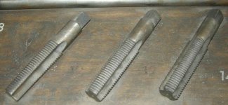
There's a good touchable display in a dark and dusty corner of the Deutsches Museum in Munich. To save you going there to look, I can confirm that the taps are relieved. This is evident from the photo of a taper tap, which I’ll attach if I can remember how to. The Munich examples date from 1856.

Seeing those tools in Munich made me appreciate what a boon it must have been, to be able to buy, for the first time, a set of standardized screwcutting tools in any enlightened city in the world.

Accepting that three is a common number of flutes, I was surprised to see some J. Whitworth taps of many flutes at Munich and London. It turns out that they were master taps used for cutting the threads for the guide stocks. Don’t ask me.

The London Science Museum’s display was described in their 1920 catalogue, transcribed below. I’ll include the reference to Bodmer’s taps as well (not on display as far as I know):-

117. SCREW STOCKS, DIES, AND TAPS. Contributed by
Messrs. Joseph Whitworth & Co., 1857.

These tools embody the improvements patented by Sir Joseph Whitworth
and John Spear in 1840.

The set of dies consists of three pieces, a wide one which acts chiefly as a
guide, and two narrow ones which act as true cutting tools or chasers. The two
cutting dies have each one cutting edge, but one cuts during the right-handed
rotation and the other with the left. Both dies are simultaneously closed in
radially by a notched cotter, which is tightened up by a nut as the screwing
advances. The master tap, by which the dies are cut, is made larger in diameter
than the ordinary tap by twice the depth of the thread, so that when commencing
to screw, the dies touch all round the rod to be screwed, and are therefore certain
to start a true thread. As the screwing proceeds, the dies act more and more
by their corners or cutting edges only, so obtaining " relief " to the cutters, and
improving their cutting power. Dies for various threads can be fitted in the
stock, and they are held in position by a removable cover-plate.

The taps are formed with three wide longitudinal grooves milled in them,
the section left being such as to give three true cutting edges of 90 degrees, and the
necessary relief is obtained by " backing-off " the thread following the cutting
edges. The shank of the tap is reduced so that it will pass through the hole
tapped. The master taps shown have eight narrow grooves, owing to the dies
to be cut being in pieces.

The adoption of the Whitworth standard screw threads which gave the
present uniformity was hastened by the superiority of this tackle over that
formerly in use. Inv. 1857-8.

118. SCREW TAPS. Contributed by R. Bodmer, Esq., 1857.

These "convolute" taps, patented by Mr. Bodmer in 1841, are very similar
to those of Whitworth. The top of the thread is eased in a convolute form,
and the bottom and sides of the thread are also tapered and relieved in the same
way, so that the tap may cut like an ordinary turning tool. Inv. 1857-7.


Whit taps04.jpg Whit taps03.jpg Whit taps05.jpgWhit taps02.jpg
 
Tom,
Apologies for not responding earlier. I no longer visit PM, but a member told me about your question, so here goes:.........
.........

Thank you so very much for replying.
This information is very helpful to me.
Thanks again.
Tom


Back
Top