What's new
What's new

Christohper Polhem's early automatic gear cutter

rivett608

Diamond
Joined
Oct 25, 2002
Location
Kansas City, Mo.
Christopher Polhem (1661-1751) was a brilliant engineer....... they had a room devoted to him in the Tekniska Museet in Stockholm....


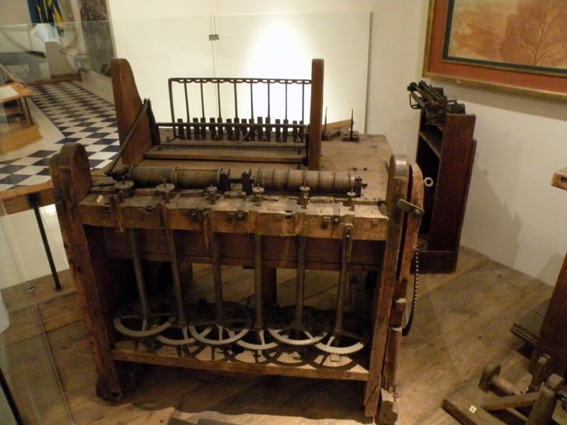
In the exhibition you find Christopher Polhem's cutting machine for making cog wheels for clocks. It is counted as the world´s first automated machining tool. At the beginning of the 18th century, Polhem operated a manufacturing works in Stjärnsund in Dalecarlia, a province of Sweden. In addition to the cog wheels, the works made plates and locks using automated machines.

The Mecanical Alphabet
This exhibition also displays Polhem´s Mechanical Alphabet, a number of wooden models that describe a range of technical design elements. The Mechanical Alphabet was used in teaching at the Laboratorium mechanicum – Sweden´s first school of technology – and later also at the Institute of Technology, the predecessor of the Royal Institute of Technology of Sweden (Kungliga Tekniska Högskolan).

http://www.tekniskamuseet.se/1/864.html

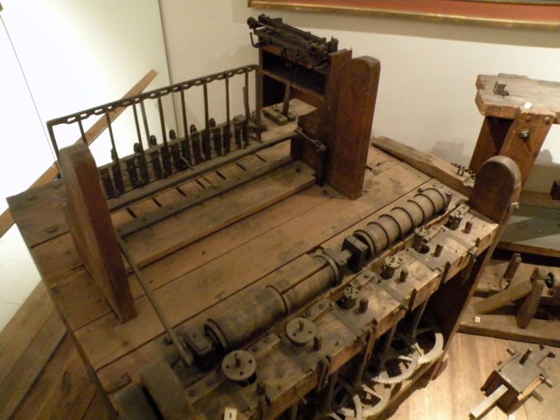
Here is his Automatic gear cutting machine...... sort of early CNC.......

DSCN4540.jpg


The cutting spindles.....
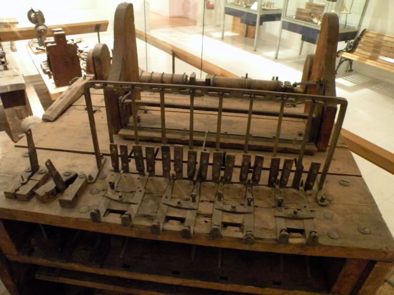
DSCN4537.jpg


The brian box......

DSCN4538.jpg


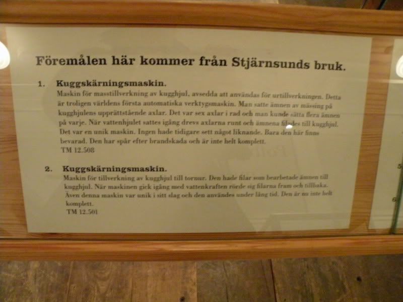
Description in Swedish.....

DSCN4539.jpg
 
I looked at this machine in Stockholm recently, and took numerous photos with a view to figuring out how it worked. I was left with more questions than answers.

The museum’s description of ‘Polhem’s automatic gear-cutting machine’ states that it was powered by a water wheel and operated by one person. ‘Entirely automatic it could 18 cogwheels at the front and 9 at the back. …. In just eight days someone could manufacture the cog wheels needed in Sweden for an entire year. …. But the clockmakers were not so interested in Polhem’s ready-made cog wheels. They wanted to continue as before and file the cog wheels by hand’.

Well, someone was interested in this machine. It is clear from the degree of wear that it had a long and busy life.

All the other 17th – 18th century clock wheel cutting machines I’ve seen were of finely-made all-metal construction. They only cut one wheel at a time, and were hand-powered. They had division plates to allow for cutting different numbers of teeth.

In contrast, the museum machine was water-powered, cut batches of gears at a time, but had a limited number of teeth options, and it was crudely made.

The difficulty in figuring out how it worked is partly due to the absence of some important parts.

I have a book called ‘Christopher Polhem – The Father of Swedish Technology’ translated from the 1911 Swedish original by William A Johnson, 1963. This includes a brief description of two gear cutting machines and a simple drawing of one of them. The drawing does not represent the machine in the museum, and only limited help can be gleaned from it or from the text.

The machine in the museum uses two distinct processes. One is a milling process using rotating discs (saws or files or milling cutters). The other uses reciprocating files (Johnson calls them broaches).

We'll consider the milling machine first, in the next post.
 
JD 2018 Polhem17.jpg1 JD 2018 Polhem04.jpg2 JD 2018 Polhem07.jpg3 JD 2018 Polhem23.jpg4 JD 2018 Polhem24.jpg5

The milling machine has two mandrels carrying toothed discs, with wooden spacers in between, rather like a milling machine arbor. The assembly is tightened by driving in tapered cotters. The mandrel was probably turned by the gear train seen in my photo 1, but the final pinion and drive shaft are missing, as is the input pinion. On the non-drive end of the mandrel is a connecting rod with its ‘wrist pin’ attached to a rocking frame (which serves the reciprocating files on the other side of the machine). See photos 2-4.

On the rotating cutters, teeth are just visible on the flanks as well as the rim (photo 5), implying that the wheels are gashed and the teeth finished on this machine, rather than just being gashed and passed on for finishing.
 
Milling machine continued

JD 2018 Polhem02.jpg 6 JD 2018 Polhem03.jpg 7 JD 2018 Polhem05.jpg 8

Now, turning to the six vertical spindles: a stack of gear wheel blanks (three?) would be mounted on the top of each spindle. The spindles are rotated incrementally by the large ratchet wheels (photo 6). I don’t know what the pawl arrangement was. It’s difficult to count the teeth, but there seem to be five or six different numbers, between 64 and 100, which doesn’t seem a very large range for clocks….?

The top end of the spindles must be able to swing towards the cutters, and should come up against a positive stop when the correct tooth depth is reached. I’ve no idea how this is accommodated. The six leadscrews are no doubt implicated. The cutters probably ran a bit out of true on the mandrel, so the depth stops would have to set to the suit the maximum throw.

There are other bits of protruding gubbins near the top of the spindles, whose role remains a mystery to me.

The spindles must move up and down relative to the gear wheel blanks. This might be done by raising and lowering the whole front frame which carries the spindles, but I can’t confirm this.

So, having speculated on various aspects, how would the machine cut gears automatically? We can imagine the spindle frame moving slowly up and down, and at the same time the operator is slowly advancing the gear blank stack against the cutter, until the depth stop is reached. Was one spindle moved at a time, or all together? Were the cuts taken to full depth in one go, or were there incremental shallow cuts? There would be some logic in the latter approach, as W A Johnson writes that quality control involved using a toothed ring gauge to confirm the correct dimensions. Also, cutting incrementally would even out the effects of milling cutter wear.

Having completed one cut, the unseen pawls must act on the ratchet wheels to rotate the spindles through one increment, ready for the next cut. Was this done automatically when the spindle was withdrawn, or did the operator have to make it happen?

That’s as far as I can go with that side of the machine. Moving to the other side, in the next post, we find even more puzzles, and I’ll invoke missing parts to excuse my shortcomings.
 
Filing cabinet

JD 2018 Polhem15.jpg 9 JD 2018 Polhem11.jpg 10 DSCN9912 (2).jpg 11

This side is basically a filing machine. See rivett’s 3rd photo.

On the left are two vertical files (photo 9) which are worked by levers underneath (photo 10). In his description of another of Polhem’s gear cutting machines, Johnson says that files were moved away from the work piece on the idle (upward) stroke. The hole in the top of the file lever is probably for spring-loaded string to pull the descending file against the workpiece.

Nearest the camera in photo 9 will be seen the top of the spindle for holding the gear blank, while photo 10 shows a ratchet wheel at the bottom end of the spindle. This has far fewer teeth than those on the ‘milling machine’ side.

Moving to the next part of the filing machine, there are eight sets of guides for eight horizontal files. One file holder can be seen protruding between its guides (one fixed guide, one adjustable) in photo 11. Note how a peg in the other end of the file holder engages with the rocking frame at the back (worked by the connecting rod on the milling machine spindle).

How the gear blanks (it that’s what was being addressed by the horizontal files) were held and indexed round is anyone’s guess. Guess, anyone?
 
#4-#7 Asquith
"and I’ll invoke missing parts to excuse my shortcomings."

The shortcomings are in the biography, I have a copy. The appended bibliography therein shows there is much more material on
Polhem available.
This was the only book in English about Polhem that I could find.
Time to learn Swedish or re-learn my sixty year old grammar schoolboy Latin?

The biography is subtitled "The Father of Swedish Technology". If all the material was available in English the subtitle might need
changing to "The Father of European Technology" or even "The Father of Technology".

From creating gauge blocks before Johansson to creating interchangeable parts before Eli Whitney failed to, there are
important developments for which Polhem is not receiving due credit.

Your practice of numbering the photographs should be adopted throughout PM.

Digression.
An improved form of what is now known as The Bazeries Cylinder was invented in Sweden c1786 (ie before Thomas Jefferson) by
Fredrik Gripenstierna. I have read somewhere that Gripenstierna was Polhem's son-in-law but I can no longer find the link.
Have your researches uncovered a connexion to Gripenstierna?
 
I was keen to learn more about Polhem's gauges. Looking at the snaps I hurriedly took of Polhem-related items in glass cases, I find that there was a ring gauge (for checking a gear wheel) and another gauge on display, but frustratingly my photo is out of focus!

However, I’ve found photos of the ring gauge on the Tekniska Museet website, and you can zoom in for a very close look.

Tolkring for kugghjul -


Tekniska museet /

DigitaltMuseum


The gauge is for a 2” dia wheel with approx. 100 teeth, so it is consistent with gears made on the milling machine.

Looking closely at the photos shows some very slight inconsistency in slot depth, but it remains a remarkable achievement considering the equipment and techniques available at the time, i.e. filing.
 
#10 Asquith
I have "zoomed in for a very close look" at the ring gauges.
Without understanding the purpose of the three (presumably symmetrical features @ 120°) on the external diameter.
Elucidation appreciated, if you can provide it.
 
Manic,

I don't know. Note that gauge photo 3/5 shows chamfers on one corner of each of the 6 slots.

A long shot: suppose that the gauge was one of a series of similar gauges kept on an inspector's bench, all looking much the same. They could be stored in circular recesses, clearly marked with the teeth numbers. Having different numbers of slots on each gauge and its storage recess would avoid mixing them up. The chamfers might help the gauges to drop back into their hole?

Neither to I know why photo 2/5 shows '20' engraved near one of the tooth slots.

The ring is about 4" diameter, which is why I think it was used by an inspector, rather by the operator during the cutting process, as you'd have to withdraw the gear too far from the cutter to get the gauge over it.
 
#12

Various means of storage may be used to protect valuable gauges and facilitate their retrieval and replacement. This might include numbering draws, shelves, recesses etc.
But before this the gauge itself would have its specification permanently stamped thereon.
At least it would if I had made it; so that next time I went to the bench after an interruption I did not wonder whether it was 97 or 98 teeth, and then have to count the teeth, again.
But they are not identified, so I am missing something or my assumptions are wrong.

You noted that the machine was "crudely made". This was not Holtzapffel making a rose engine covered with guilloché for the royal family and charging accordingly. When every operation was arduous, difficult, and frequently dangerous, I assume that parts with superfluous features were sedulously avoided.

Possibly someone had to reach a judgement using incomplete information (like we are) decided that the item was a gauge and it has been so described ever since.


Back
Top