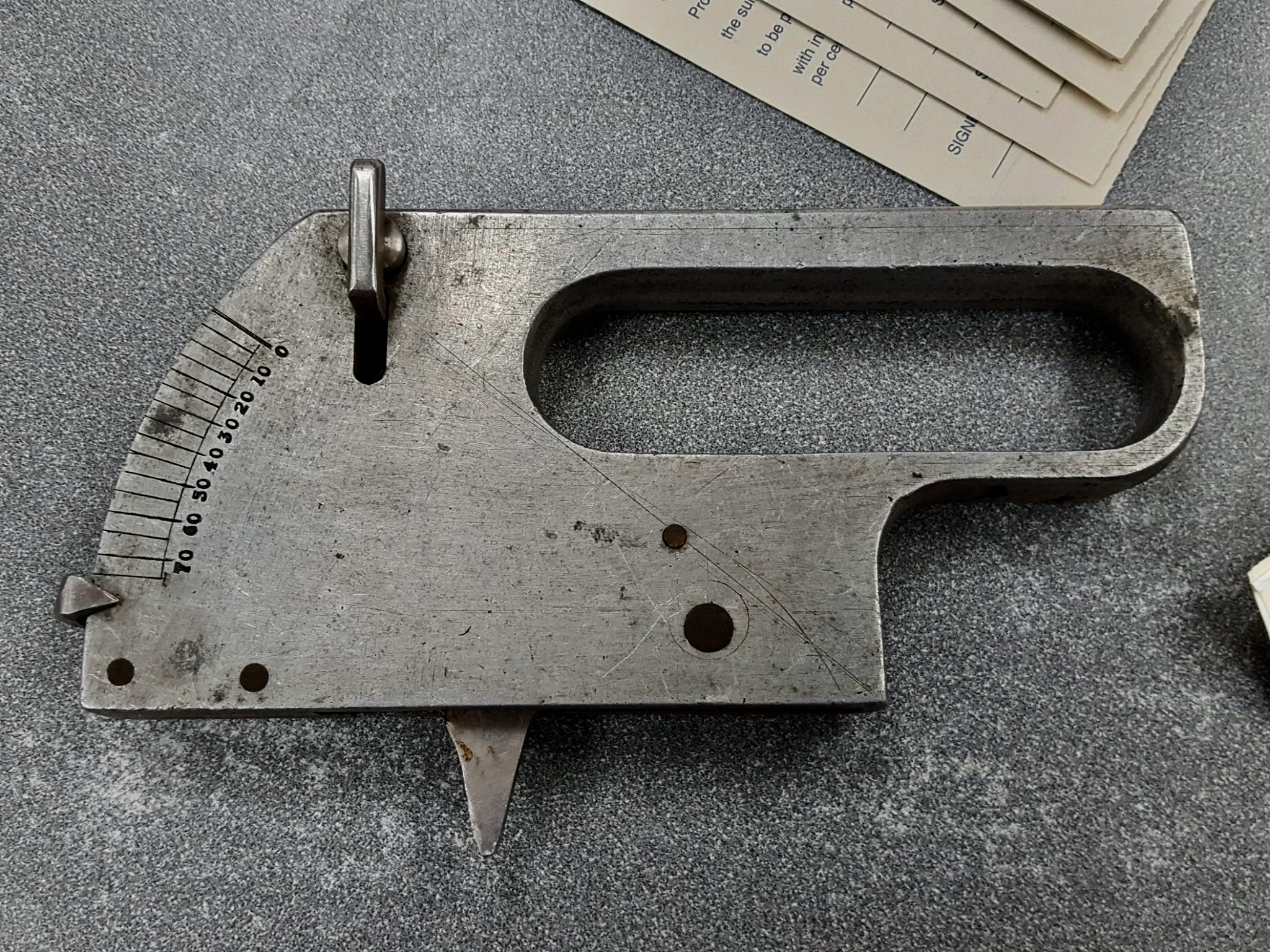
A visitor to another forum posted this photo with no other info, then disappeared. Wanted ID. Now, so do I. Looks like you set and lock an angle on the scale and the straight edge of triangular piece takes that angle. Anybody seen another one of these? Sry, no dimensions avl. Maybe the fact that it is only marked up to 75 degrees will help reveal the original purpose.
Last edited: