What's new
What's new

Fairbanks-morse cylinder liner

pondracer

Plastic
Joined
Jun 12, 2017
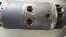
I was given a cylinder liner from one of the Fairbanks 38D8-1/8 engines that my local power plant had, and am doing some research and design in order to turn it into a mancave lamp.

I plan on making a base out of 4x4 timber, and a support skeleton internal to the liner out of black iron pipe.

My question is: whst is the diameter and thread guage of where those injector glands go (middle of cylinder liner)? Trying to figure out how I can attach the skeleton using those injector ports as a means to mount the skeleton on to the liner. Ive tried contacting FME through their helpdesk but heard nada from them.

Thanks in advance,
PondRacer
 
If you had no ready-made means of gauging the threads, there are a few ways to go about determining what the thread is.

1. Determine the pitch (threads/inch): use a thread or screw pitch gauge, and see how many threads/inch the injector port threads are.
If you do not have a screw pitch gauge, you might use a series of bolts of various pitches, not to get the actual thread size/pitch,
but simply as screw pitch gauges. Use the bolts to see which thread pitch drops in and matches up to the pitch of the threads in the
injector ports. Obviously, the bolts will be a lot smaller than the injector port diameters.

2. Using something like a telescoping gauge, "capture" the inner diameter of the injector port and then use an outside micrometer to
mike across the telescoping gauge. This measurement will give you the "root diameter" of the threaded hole.

3. Do the math to "work backwards" from that root diameter. I.E.: if you have determined how many threads per inch the port has, then,
Depth of thread = 0.6495 x (1/n) where n = number of threads per inch.

Outer diameter of the thread = (root diameter) + ( 2 x Depth of thread)

4. Put the number of threads/inch, determined in step 1, above, together with the outer diameter calculated in step 3, above,
and you have your thread data.

5. Get a chunk of scrap steel or aluminum and chuck it in your lathe. Turn one end slightly larger than the root diameter you
miked, and keep skim cutting and trying it in the threaded bore until it just enters snugly. Re-run your numbers using this
diameter to get the "final" outer diameter of the injector body thread.

6. Turn the other end of that piece of stock to the "final" outer diameter as determined in step 5, above. Then, using your lathe,
set it to cut the number of threads/inch you determined in step 1, and cut the thread to the depth calculated in step 3, above.
This piece of scrap is your gauge. Try it in the injector ports. If need be, set it back up in your lathe and "pick up the thread"
with your threading tool and skim a few thousandths off the threads and re-try it on your cylinder liner ports. If it enters
with a good fit, not too tight, not too sloppy, you are there. Note how deep you finally cut the threads.

7. Get some steel round stock like A-36 hot rolled (which is readily weldable), and machine two diameters to the OD of the threads,
leaving a good shoulder. Use a parting tool or a toolbit ground to cut a "neck" with a radius'd end, cut a groove or undercut\
at the base of the shoulder. This will let you run the "plugs" you are making into the holes and seat them solidly.
Cut the threads to the depth you noted and put a chamfer on the ends of threads and you are there.

8. Cut the larger/unthreaded sections of each plug to whatever length and size you need for attachment to your support stand.

9. Cut some soft copper (roofing flashing works for this) to make gaskets for your "plugs". Anneal this soft copper. Run the plugs in
tight using a pipe wrench on them. The soft copper is what F-M used for injector gaskets. It will help seat the plugs you made
solidly against the cylinder liner.

10. Weld whatever you decide upon to each projecting plug to support the cylinder liner.

11. If you choose to support the cylinder liner from within:
-make the plugs as detailed above, but mill hex flats on them where they project on the outside of the liner, or machine them
to suit your own eye and ideas.

-make the threaded sections a bit longer.

-either make some nuts to screw onto the threaded sections, or drill/tap down the center of the threaded section of each plug for a bolt.
The heavier the better.

-cut come "clip angles" from heavy steel angle iron, drilled to slip over the threaded sections of each plug- if you made nuts to fit
them. Or, drill the angle to pass over bolts that will be screwed into the ends of the threaded portions of each plug.

The longer you make the threaded ends of the plugs, the higher the bending stress will be in them if you support the liner from inside
it.

-attach your support stand to these clip angles. I imagine you want to put the support stand inside the liner so it appears to be
floating rather than having a stand outside it. A-36 steel is machineable and weldable and cheap. I'd steer clear of cold rolled
as it is not the best thing to run structural welds on.

I can't resist adding this thought: Rather than your going thru all the steps to determine what thread is in the liners, perhaps you can ask
your buddy at the powerplant to borrow a spare injector. You can then get the thread data from it and save some work.
 
Troll or not, I am curious to know whether there are cracks radiating from any of the threaded ports. I have seen this on several of these liners from different installations. The cracks result in combustion gases in the coolant. The duel-fuel version of these engines added ports for the gas valves, which weakened the liner. They rely on the shrunk-on water jacket, which is heat-treated steel, for integrity. They are susceptible to fatigue cracks growing from corrosion pits, so water chemistry has to be watched closely.
 
My response is a knee-jerk reaction to a question about determining what thread size is. If the OP (sorry for the pun) is posting about a cylinder liner from an OP Fairbanks engine, not in regard to the engine or its repair/restoration or a technical question as to its operating principals, then I agree- he is off base for this forum. If he wants to decorate his man cave with an OP Fairbanks cylinder liner, he may be one shade removed from the breed who pulls cast legs off old lathes for "industrial look tables". Point taken and I stand informed and corrected. Let him take some hardware store gradew black steel fittings and sch 40 pipe and some hardware store grade bolts and similar and wrestle with the liner. I will confine my comments to stuff related to the machine tools or at least to the repair or engineering principals of machinery and engines and boilers. There's enough people out there with the steam punk mentality to do some serious damage to the remaining old iron-
 
Okay, so I'm one step removed from the guy who removed legs from old lathes to make tables out of? Okay... For your information, the cylinder liner came out of a power plant engine (they had 4) that was decommissioned and sold for scrap (part of LEED Gold mandate for power plant overhaul/upgrade). I would have liked to have an entire 12cylinder engine but my backyard is not big enough for such a beast that stands 10ft tall 10ft wide 40ft long (with generator head).

Just so you know, I heard back from FME, finally, and they said that 3 of those injector holes are 1 1/4"-12UNF and the 4th is 1 1/2"-12UNF. Not easily found in the big box stores but not too difficult from Grainger, mcmaster-carr, et al. All it is, is just an internal skeleton to mount the liner on, no permanent changes made to liner itself.

John Michael's was halfway helpful in his first post and I appreciated the idea about the copper washer (never knew that, thanks!). After that it kinda went downhill, with each new post being less than helpful. Kinda gives me a negative impression. Maybe understandable given that I may have posted in a forum that is not necessarily about repurposing old things, but I didn't know where else to post but here. Yes, I did look - carefully - using search features but this forum subject (antique engines) seemed to be the best fit.

So, before you make snap judgements about new people posting, you may wanna consider your words, because with how you treated posts like this could be a big turnoff for those who are considering getting into machining or woodworking or what have you as a hobby - or occupation.

So, have a good day. If you never see me again, DONT be surprised, because of what YOU have said.

PondRacer
 
TDMidget,

An interesting question comes up when your reply is considered together with this phrase from the OP in Post #11"
" decommissioned and sold for scrap (part of LEED Gold mandate for power plant overhaul/upgrade). "

I've heard of environmental programs which REQUIRE destruction of the equipment being removed. It's analogous to "Cash for Clunkers", where the engines of the cars being turned in had to be destroyed by, IIRC, running them to seizure with the oil replaced by Sodium Silicate.

Fabworks:
That pitch gauge says its for the 55 degree inch system and the 60 degree metric system. That 55 degree inch system is the British Empire system. The US Unified National thread system that includes UNF would be properly referred to as a "60-degree inch-based system", although why a vendor would refer to it as anything other than Unified National is beyond me.

The 55 vs 60 might not matter much on a pitch gage. The 55 will fit in the 60! :)

John Ruth
 
Unified, not unified national. The whole idea was to do away with separate systems by nation and standardize the U.S. , Canada, and Great Britain.

As I understand it Fairbanks buys them back and upgrade as new.
 
Last edited:
Thank you, tdmidget. Being a pedantic old goat, I want to scream when I see / hear / read "Unified National" (especially in a textbook or other supposedly-authoritative document).

I came by it honestly. My apprenticeship instructor firmly believed that to work precisely you must communicate precisely. He would give tests with pass/fail questions. You might have 49 out of 50 correct but if you didn't know the difference between a jig and a fixture, an arbor and a mandrel, a bolt and a screw, the proper terms for each machining operation and so on, that one question would fail you. You could not retest for 2 weeks. I am thankful to have had him for a teacher.
 
Antique machine and history is an "Open Discussion) forum. No Off topic prefix required for posts and/or opinions. Note that the post was replied to by several members and provided methods to satisfy the original poster and provided a learning opportunity for all members.
 
While TD comes through a bit on the grumpy side, I agree with his basic tenant. One clown used to drive me crazy with statements like "Put this piece of Bakelite in your lathe and spin it down 1/8 inch." As we all know (or should) spinning has a lot of meanings in general use but when used in relation to a lathe it means a specific operation. Another of his gems was that an airplane's engine would not run inverted because it did not have a pressurized fuel tank, meaning exactly nothing. I think he picked up the term "pressure carburetor", which is what chainsaws, among others, use and mixed it with fuel tank. The point is that the same inaccuracy came through in his efforts at problem solving. He was incapable of following a logical sequence if A then B, resulting in C.

Pondracer, if you are thin skinned, you will not last long around here. You are complaining and you haven't even been Weldenated yet. Remember that this is a forum for folks who make their living making chips and 40 year machinists are common. Many have spent lifetimes breathing cutting oil smoke and dodging hot chips, working in one of the most dangerous environments on the planet. Most have kept all their fingers while doing it and take some justifiable pride in the accomplishment. "Politically correct" doesn't fly very far here.

OTOH, this represents one of the greatest repositories of knowledge south of the Library of Congress. The total experience of the members laid end to end would reach back to the last ice age, so don't go away mad, just go along with it.

Bill
 
So what is the difference between "unified national" and "unified" other than the fact that the latter is their attempt to do away with the 'nationalization'? I know that UN came in fine and coarse threads.

At least I'm not working with Whitworth...

PondRacer
 
There is NO such thing as "Unified National" . Never was. In 1949 the governments of the U.S., Canada, and Great Britain agreed on "Unified" threads, abbreviated as "UN". This was to eliminate some of the problems encountered in WWII when producing war materials for a common military effort. The ignorant have been sticking National in there since , I guess. In this country Unified threads replaced SAE for fine threads and United States Standard for coarse threads. The thread profiles are, I believe , the same as metric threads. Since both Canada and Great Britain have gone metric I believe that it leaves the U.S. and some little Asian shit hole as the only subscribers to the standard
It really doesn't matter much to a machinist. With the right equipment you can cut any of them.


Back
Top