What's new
What's new

Hendey 14x6 lathe

toolguy07

Plastic
Joined
Sep 3, 2017
Location
Holland
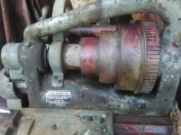
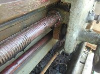
Hi all this is my first post. I bought this lathe off of craigslist. it was in a dirt floor pole barn in Muskegon Michigan. I have read as much as i could about this lathe on this forum. The serial number appears to have been destroyed at some point, i am guessing the ways were reground and they never bothered to re-stamp the serial between the ways.the machine is a mess after sitting for a decade according to the guy i bought it from. it was used by his uncle to make parts for old flathead engines. i am not sure of the year. the "Hendey" name is not cast into the tiebar and no size casing in the bed. if Hendeyman is able to let me know anything i would really appreciate it. it has stuck spindle bearings and will have to go through a total rebuild due to fine sand dust on every square inch of it. it came with a drive-all gearbox and 3hp motor. enjoy the picks:)KIMG0313.jpgKIMG0318.jpgKIMG0319.jpgKIMG0320.jpgKIMG0321.jpg
 
Welcome to forum. Early twenties / late teens as a guess

Missing lead screw reverse lever lower right hand side of apron.

Missing oiler for front spindle bearing (see down low hole) suggests no PO in living memory had a clue of how the oiling took place

Here is "manual" scan in case needed. Thanks to Greg Menke for hosting it for me.

http://pounceatron.dreamhosters.com/docs/hendey/1920-Hendey-manual.pdf

Here is my old write up on the neat lead screw reverse system

http://www.practicalmachinist.com/v...ory/hendey-lathe-emergency-113621/#post421468

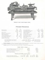
Thumbnail catalog page for 12 and 14" from those days
 

Attachments

  • 12 and 14.jpg
    12 and 14.jpg
    92.2 KB · Views: 302
Thank you Johnoder for your reply, the reversing lever was broken off during loading on my trailer i will have to braze that back on. As far as the oiler missing i am not surprised to hear that parts are missing a crude sheet metal guard was fitted to the lathe when the driveall transmission was put on which covered most all of the oil ports including the spindle oil ports. thank you for the manual scans. this poor lathe had at least 4 inches of oil and swarf in the pan that i cleaned out before moving it.
 
Here are the usual helpful images for head stock disassembly - invariably needed for draggy/bindy/stuck front spindle bearings - a "standard" old Hendey issue (assuming it has tapered spindle bearing journals)

Other than the mentioned shimming, folks have ALSO used TIMESAVER compound to correct the problem
 

Attachments

  • Spindle Removal Instruct.jpg
    Spindle Removal Instruct.jpg
    115.1 KB · Views: 174
  • Spindle With Alphas.jpg
    Spindle With Alphas.jpg
    95.8 KB · Views: 491
  • Spindle.jpg
    Spindle.jpg
    82.4 KB · Views: 273
  • All parts.jpg
    All parts.jpg
    89.4 KB · Views: 246
  • List.jpg
    List.jpg
    89 KB · Views: 159
Last edited:
toolguy07:

Your lathe appears to be a 16 inch model, built before 1915. Because of certain features of the Apron, it was most likely built between
1906 and 1911. Another indication that this is a 16 inch lathe is the use of the 46 tooth gear in conjunction with the No.2 position on
the Compound Gear Box to produce the 11-1/2 thread. This combination was used on the 18 inch and 20 inch lathes, but the Apron design
favors the 16 inch lathe. It will required more information on the various parts to determine a more accurate circa of manufacture. There
are no longer any Patterns, Castings or Repair Parts left in inventory for this lathe, but all of the original drawings are still in the
files, so parts can be made as required. If you will measure the Center Distance with the Tailstock flush with the end of the bed, I
should be able to give you the official Bed length.

Hendeyman
 
Thank you Hendeyman for your reply i will get that measurement later tomorrow. i have some more pics i took that shows some more detail. and for the people that will wounder what the red stuff over everything is, it is red tacky grease to stop the surface rusting that was well underway when it was in the dirt floor barn where i rescued it from. if it is the 16 inch model that explains why it is so heavy, they sure knew how to build machine tools back then.

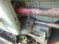
IMG_20170922_175059.jpgIMG_20170924_162840.jpgIMG_20170924_162849.jpgIMG_20170924_162906.jpgIMG_20170924_162918.jpg
 
toolguy07:

Thank you for the additional pictures, I can now give you a more exact date of manufacture. The critical bit of information I was looking
for was on the Index Plate. The picture you posted of the Index Plate in your original post, did not show the lower right hand corner
clearly. The second picture you posted of the Index Plate clearly shows the Feed at 5 times, that along with the 46 tooth gear to cut the
11-1/2 thread fixes the year of manufacture at 1905. While it is true that the 5 times rate was standard on the 16 inch Cone Head even in
1898, the gear combination changed in 1904 with the introduction of the Compound Gear Box. Your lathe is an early Tie Bar, which means
that it was built in 1905 or later, in fact Tie Bars were built during WW2. The limiting factor in this case is the fact that the Engineering Department started the design work on the new Geared Head Lathe and several thing were done to standardize the Cone Heads and
the Geared Heads. As early as September 24, 1903, Leadscrews were being converted from seven threads per inch to six threads per inch.
By June 20, 1905, even the 12 inch lathes had been changed over. Another simple test for a 1905 lathe is to check the Intermediate Gear
to see if it was fitted with a Bronze Brushing, these became standard after February 1, 1905. Now for the clincher, by 1906 the Index Plates were changed to read 6 Times instead of 5 Times. There is an Engineering Department note to the effect that some lathes with Serial Numbers between 6600 and 7022 may have the older Leadscrews installed, please check the number of threads on your Leadscrew. These Serial Numbers represent lathes built between October 1904 and May 1905. This is just another way to determine the manufacturing date without the Serial Number.

Hendeyman
 
hendeyman to answer your questions the lead-screw is 7-tpi. between centers is 33 inches snout to tail-stock. also please forgive my ignorance but which gear is the intermediate gear? i also located an aluminum tag riveted to the headstock with what might be the serial number it is 413300, but this could also be an equipment id tag i suppose the tag was damaged when they drilled through it to fit the sheet metal belt guard so i am not sure if the 1 is correct. i cant wait to get this beast making chips again.
 
toolguy07:

Refer to the fifth picture of your original post, just below the hole in the Spindle is a gear that looks like it has a flange on it, that is the Intermediate Gear. It connects the Spindle Gear to the Sleeve Gear and is held in mesh by the rotation of the Spindle Gear and is disengaged by pulling to the left of the Headstock until it clears the other gears. There isn't any detent used to locate it in either position.

If you measured the Center Distance from the Spindle Nose to the Tailstock Spindle Face with both the Tailstock flush with the end of the
bed and the Tailstock Spindle flush with the Tailstock Casting, sans Centers, then this would be a standard 6 foot bed. It would have
been nice if this had been a seven foot bed, it would make searching through 400 plus Serial Numbers a bit easier as not many seven foot beds were built.

Hendeyman
 
Hendeyman the intermediate gear does have the bronze bushing. another question i have is what is the function of the intermediate gear? the reason i ask is that it appears the original owner never moved this gear at all i had to pry on it to disengage it.
 
toolguy07:

The Intermediate Gear serves two functions. It allows for a simple method of disconnecting the Spindle from the leadscrew when you don't
really need to have power feed or screw cutting available, but its most useful feature is for indexing Multi-start threads. The 1918-1920
Operator's Manual, owned by Johnodor and hosted by Greg Menke, explains this method. Even if your lathe did not have the graduations on
the end of the Spindle, it is only necessary to remove the Gear Guard and "chalk" the teeth on the Spindle Gear for the number of starts
required and you can start cutting Multi-start threads. The Intermediate Gear can be taken out mesh and the Spindle indexed without disturbing the relationship between the Spindle and the Leadscrew. Make certain that the Intermediate Gear and the Intermediate Stud are
well oiled. Keep in mind that as long as the Chuck runs "over", that is counterclockwise as viewed from the Tailstock end, the Inter-
mediate Gear will remain in mesh with the Spindle Gear and the Sleeve Gear.

Hendeyman
 
tooguy07:

During the 1905-1906 period, the 16 inch lathes used a Morse Taper No.3 for the Center Bushing and the Tailstock Spindle. The exterior
taper of the Center Bushing is Morse Taper No.4-1/2. All were standard sizes when your lathe was built, but the "half sizes" seem to be
obsolete. I have all of the original Hendey Taper Gages that cover all of the Morse Tpaers from No.2 through No.6 by half sizes. If you
decided to make your own Center Bushing I can send you the dimensions, it will not be necessary to harden and grind it for the limited
use you will give it.

Hendeyman
 
I was able to follow the steps of removing A, then K, then L but now I'm stuck with E. There are two "E" collars on my lathe and I can only get the one on the right to move about .25 rotation in either direction before it locks up. Even after doing so, the one on the left does not budge at all. Any ideas on what is needed to proceed and remove the spindle? Here's a link to the photo as I can't upload it in the post.

http://i231.photobucket.com/albums/ee282/omansnowy/20170927_171013.png

Thanks
 
Here are the usual helpful images for head stock disassembly - invariably needed for draggy/bindy/stuck front spindle bearings - a "standard" old Hendey issue (assuming it has tapered spindle bearing journals)

Other than the mentioned shimming, folks have ALSO used TIMESAVER compound to correct the problem

johnoder I was able to remove "A, K, and L" as directed in the manual. I am not trying to remove "E" but there are two threaded rings instead of just one as shown on the drawing. I am only able to move the right one about .25 rotations in either direction but that doesn't allow me to move the left one at all. Spindle doesn't want to budge at all either. Please see link below with pictures of current setup. Any help is appreciated.

Photobucket
 
In my Private Message to you I suggested starting your own thread. I'll suggest that again here. Main page of this Antique section of the forum has the thread starting button upper left

I would expect such nuts to have set screws. If missed before rotation starts, threads are damaged. You may have to do something similar to what I had to do on this huge L&S in the link below. This linked thread has uploaded non photobucket photos at the end. And eventually you will need to make or have made NEW ring nuts. Hendeyman will have the drawings

http://www.practicalmachinist.com/v...ctive-head-work-112298/?highlight=Clutch+work


johnoder I was able to remove "A, K, and L" as directed in the manual. I am not trying to remove "E" but there are two threaded rings instead of just one as shown on the drawing. I am only able to move the right one about .25 rotations in either direction but that doesn't allow me to move the left one at all. Spindle doesn't want to budge at all either. Please see link below with pictures of current setup. Any help is appreciated.

Photobucket


Back
Top