What's new
What's new

Hendey lathe "emergency"!

Christopher

Aluminum
Joined
Jun 3, 2006
Location
Gainesville, Georgia
Good afternoon.

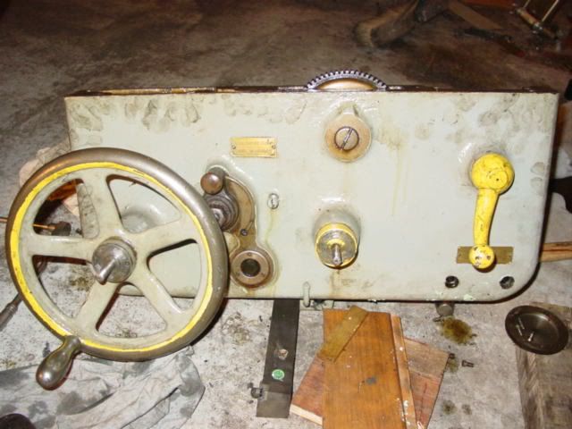
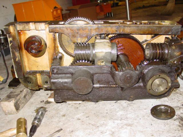
I have a customer down, (And can take until Tuesday to get the part, so it is not as bad as it could be) and the workpiece will only fit our old Hendey. (Ok, the Bridgeford is not functional yet, but my wife is here teasing me about it)The problem is that I have not taken the time to test its threading capabilities. AFter setting up some sacrificial bar of the correct size, I attempted to scratch my dye marks for pitch verification. Here lies the problem: The half nut lever is lifted to engage. It will not lift, and therefore close the half-nut, because the lockout is engaged. I went through the manual, (Thank you James) and it does not describe this well enough to diagnose. During an archive search of the PM site I found a picture of a "similar" apron that another member posted, but it was for a different issue. Below I have posted a picture of the Apron on our machine (26" gear head Hendey circa 1937), and below that is a picture of a similar apron on a different model Hendey (Thanks Rob)
Hendeyapron.jpg


Hendeyhalfnutlockout.jpg


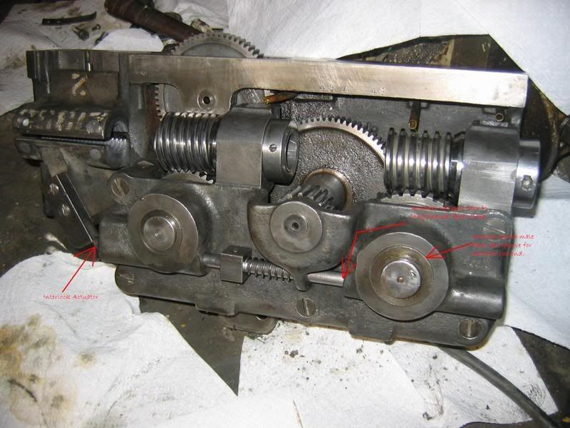
When I reach around the apron, (hold the laghter) I can feel the lockout rod, and it is indeed in position to block the closure of the nut. I am aware of its function, and can be certain that the friction clutches for feed are disengaged. I even loosened up their adjustment further for good measure. Additionally, the lead screw and half nuts are clean. This is likely a lockout issue, but I cannot get the rod to retract. I am ready to lower the apron from the carriage if necessary, but I feel as though I have overlooked something simple. Any thoughts?
 
Hi Christopher, I will start by saying I have no experience with Hendey lathes. On other lathes I have used, even though the feed clutches are not engaged, there is uaually a lever or push/pull knob to totally disengage the feed, so the half nuts can be engaged.The feed control usually has forward-neutral-reverse positions. It should be in neutral for threading.Good luck.
Tom Partington from Mass.
 
The interlock rod is "functionalized" by engaging the longitudinal apron clutch on the apron.

Your 26 has a version of a lever clutch on both cross and long feed that looks distinctly like the linked patent.

You can plainly see how the interlock rod is released into the groove when the clutch is sufficiently released by looking at sheet three of the patent. It is possible that the last person that assembled this apron put the rod in up side down. Don't think it would ever go into groove that way.

Hendey Patent 1,972,373

You will have to do what ever finagling is needed to get this clutch released enough so the interlock rod is not blocking the half nuts. This may require dissassembly of this clutch or even the apron.

John
 
Thanks John,

It sounds like you are on the right track. I have already removed the outer engagement handles in an effort to aid release, but to no avail. I am now working on disassembly as we speak. I believe it will be an entertaining Memorial day weekend!

Christopher
 
Here is another thought I got reading thru the patent.

The rod is spring loaded to right meaning it is always in the way until the half nut are engaged.

They can only be engaged if the rod can move into the groove

The thought consists of this: If you have tried to engage the half nuts, and left them that way, the rod may be pressing against the bushing with the groove in it, making it more difficult for the bushing to be moved to where the groove would allow the rod to enter

Seems like it would be sensible to make sure the half nuts were fully disengaged and the rod had moved towards the half nuts all possible before trying to get the clutch bushing to slide in or out to the correct postion to allow groove to accept end of rod.

John
 
John,

I wondered that as well, but now that the apron is off, it does not seem to be the case. In fact, I took the half nuts completly out, and removed the feed clutch handles as well. Additionally, I tapped (gently) on the rods that protrude through the handwheels to ensure that the clutches were released. None of this is alleviating the interference. I am now trying to remove the large slotted screws that fasten the back wall of the apron, and support the actual clutch assembly. That should give better access to see potential trouble.
Apron1.jpg

Apron2.jpg


Oddly enough, removing the big slotted screws are proving to be more trouble than anything else. I have already broken three tips on my "Impact driver" (the old manual hammer-type) and one nice drag link socket from the toolbox. Until a trip to the local parts house for "reinforcements", I may be forced to take a break. Thank you for taking the time to look at this. This machine appears to be relatively unmolested, and there is no evidence that this area was accessed after assembly. There was actually lead filling in the screw heads that were under the cross-slide dovetail. This was then blended with the surface of the way. Very fine way to keep the swarf out. What this means on this repair is uncertain, but I am hoping that I will not find someone's temporary fix...

All the best,

Christopher
 
Christopher,
I am not sure what the lead-filled screws you mention were for, but lead-filled could mean "do not disturb".

I found something similar on the balance weights of a stationary engine. Lead has been poured around the retaining bolt heads - I guess for a permanent lock.
 
John,

The spring slides smoothly to the right (as in towards the headstock if assembled), but there is a definate stopping point after about 3/8". It "sounds" (with a screwdriver to the ear) like it is stopping inside the housing of the carriage feed clutch. If it moved another 3/8" it would be fine, but alas there's no such luck. I will start fresh tomorrow morning. I just milled some new "screwdriver tips" from some scrap 440 Hex bar, so maybe they can be persuaded to break loose. Peter, you raise a good point; however, these two screws were two of the four large slotted bolts that fix the apron to the carriage. There was no choice but to scrape out the lead. It did its job well, and some fascimile of that will be put back to prevent future debris from collecting there.

Kindest regards,

Christopher
 
Fellas,

Thanks. John, your patent illustrations made a huge difference. The problem was actually external. There is a washer that rides under the longitudinal feed wheel. This washer is more of a shim than a washer, and is used to increase the disengagement pressure on the rod attached to the innermost disc when the feed is disengaged. Sometime between 1937 and recent, that washer was undoubtedly lost during some adjustment of cleaning. The washer that was made to replace it was too small to fit ofer the shaft freely. It was galled to the shaft in the "partly engaged" mode. This left the clutch enough room to engage and disengage, but not enough to fully retract and allow the safety rod to slip into the groove. The washer now has enough play to move freely on the shaft. Although I tapped the clutch rod inward before removing the apron, the washer held back the clouting from an 18 oz. brass hammer. In fact, after removing the apron, I had to thread an acorn nut on the rod and show it some serious love to seperate the parts. I hope to have the apron in place tomorrow, and will be glad for it. That apron is a job for two stout fellas. Thanks again for all the suggestions.

Have a great evening,

Christopher
 
I've been lurking here with interest, thinking
that 'that doesn't seem to be that big.'

Then I caught a glimpse of the impact driver
in the foreground in that one photo. Unless you
have somehow managed to find a 1/5 scale
impact driver, that is one seriously large
lathe apron!

Jim
 
Jim,

That is indeed the trusty o'l "Prima" impact driver. Our forklift forks are drilled on the ends, so we actually bolted the apron to the underside of the forks for an impromptu workstation. For re-install, it will take three people. Two fellas can manhandle the apron ok, but not while lining up the lead screw keys. JL: You are very much correct. Although prior to removing the apron, some respectable force was applied to that threaded stub, and there was no evidence that the roundish facet was a washer. It appeared to have been "turned from solid". Not until the apron was off, and the crossfeed clutch apart was the difference detected. It ended up taking some serious force from a 4lb. hammer to seperate the two parts! I do some hobby blacksmithing, and when I "need" a large hammer, there is a genuine problem. I was fairly certain that I would be making a new shaft for the transverse clutch after the force that danged washer endured. Fortunatly, the folks at Hendey used quality materials, and good heat treatment. After inspecting the shaft for straightness, and chasing the threads, it was re-assembly time. As you mentioned, however; had I known that the washer was not an "invited guest", I would not have removed the apron. On the brighter side (I try to look for it...) The oil sump in the apron had over 3/4" of jellied "shellac" and fine fibers (the lathe came from a tobacco plant), and all of the oil passages were nearly blocked. The half nuts were in no better shape either. I have determined that our 16" gear head Sidney is next in for similar "PM" work.

John, I type slow, and just caught that... I believe the threading was a very seldom used feature on that machine! Other than brownish jellied oil, there is almost no wear on any of the parts of that machine. Other than the misplaced washer, it is in very good to excellent condition. When it is running, you must hold your hand against the headstock to feel it, as it cannot be heard over the Okuma...

Regards,

Christopher
 
Chris:

If machine has not been fitted with threading dial at some point would you like some pointers on the "Hendey" system of threading?

Factory did not fit them with threading dials.

John
 
Yessir John!

I have one of John (Hendeymans')manual reprints, and the instructions are sketchy. I am not at the shop today, and don't have the manual close. If I recall, the half-nut was supposed to stay engaged, but I am not certain. Then again, I believe the LS is 2 tpi, and the thread I need to cut is 12 tpi(RH). I believe that if I set the "bed stop" at the right side of the carriage, where the thread begins, I should be able to close the half nut anywhere. There will be a large relief at the end of the thread, so I will have plenty of time to stop. Admittedly, with the clutch problem, I did not spend any time planning out the procedure, so I would graciously accept any pointers you share. Thanks in advance!

Kindest regards,

Christopher
 
basically Hendey did expect you to pitch out a lot of what you had learned (or at least we certainly have to today)

They thought you should have complete control of what the lead screw was doing at any given time.

The lever at the extreme right of apron will do these things if all the parts are working as intended (good thing to check, right?)

Down position: Lead screw turns so as to move carriage towards head stock

Middle position: Lead screw stops - like instantly

Up position: Lead screw turns so as to move carriage towards tailstock

If things are right, the lever will stay in each of these positions you can put it in. Sometimes age and wear make the little flat detent spring under the HS "go away" and the lever will not stay where you put it - so you hold it there, while also "holding your mouth right".

The setting of the stop as you mention comes from the fact that in the mid position the lead screw is stopped and you can open the half nuts (handy on a long thread) and close them again at any point and not be out of time - as long as the jiggling of carriage position to enable closing them again did not turn lead screw.

So with the above in mind:

Close half nuts (lever mid position)

Get set to make a threading pass

Push lever down - zip! the carriage moves smartly towards head stock

At relief groove, lift lever to mid position and withdraw tool from cut

When ready, lift lever to top position - carriage moves smartly towards tail stock

At your starting point push lever to mid position, and get ready to make another pass.

Repeat.

Note on this hypothetical short thread we did not open half nuts.

You could, on a long thread, open half nuts with lead screw stopped, hand wheel to starting position and close them. I suppose if you had something to stop against, there would be less carriage jiggling to enable reclosing of half nuts.

As you may know, handwheel can be taken out of engagement during threading. It is eccentric mounted and has a short lever to rotate the eccentric.


Ordinary non Hendey bystanders will be baffled to see you thus thread with the handwheel disengaged

A good point is to remember, due to backlash, it is smart to include some sufficient travel for "things to happen" before actually cutting metal begins

The "single tooth dog clutch" under head stock works marvelously - but is not for banging and crashing at elevated speeds.

You can set stop on stop rod to cause the lever to move to mid position - and stop lead screw. Handy for internal threading to a shoulder with hardly any "pucker factor"

John
 
A sincere thank you John. I will print these and add them to the manual! I do not remember the specifics, but the manual gives a maximum spindle speed for reversing the lead screw. I have never tried the stop rods, but if it works anything like the one on the LS Okuma, it will be a pleasure to use. I do indeed have a shoulder on the current job, so I may practice with some scrap and try it on this part. The current part is a simple chrome hydraulic cylinder rod (3" X 76") that gets about 7" of 2.5"-12 threads and a couple of wrench flats. Other than the simple weight factor, it will be straight-forward. With the new machine layout, we will be fabricating a light bridge crane system to assist with things like this. Although the rod is close to 200 lbs, I think it is still bested by the steady rest! Two stout fellas are necessary to gey it safely set.

Thanks again for the generous tips. I would love to return the favor somehow. We've got some great sourwood honey locally if you are interested? Any requests?

All the best,

Christopher
 
Chris, Glad that the Hendey problem was solved. Thought the external problem ended up being very simple, you no doubt feel good about getting the sludge out of theapron oil sump.


Recently I had the necessity to take the apron from our raised 18 by 78 in order to clean out the gunk and fine metal particles, about 3 inches deep. I too ran into the problem of removing the screws from the back side of the apron wall, and broke several tips from identical impact drivers.

You are right on about Hendey quality... top drawer. Even with the lack of clean oil in the apron, all internal parts were pristine, believe it or not.

One surprize was finding several of the gears clearly marked "UK". Were these made over the pond? Did Hendey have a plant in the United Kingdom?
 
Thanks.

I have no idea about the UK marking. Is is possibly an internal QA stamp, or individual trademans' mark? I do not know what would have been customary then. Regarding the screws... We milled a few from pre-hard 3/4" 440 ss hex bar. That coupled with some repetitive "tapping" or successive sharp blows from a small hammer, and it still took a 24" hingehandle! If you ever have a problem like that, Take the time to cut some hex-shaped slot drivers. I cut these "At" or maybe .001" over the slot width, and they did not seem inclined to climb out of the slot. The "drag-link" sockets from the tool companies snapped like toys, and were hard to keep engaged in the slot. Additionally, we had to made a tool to hold the leadscrew drive sleeves in place (internally) while the LH threaded lock collars were backed off with rawhide mallet/spanner. The tool was essentially a deeply keyed shaft, whose OD was just under the lead screw od. The tool was then cross drilled to accept a chunk of 3/4" alum. bar. Anyone with a similar machine can borrow the tools if you need them. That is supposing you have a Hendey with a 1 5/8" screw. You will save possible damage to the worm gear with pliers. Those collars were tight!

All the best,

Christopher


Back
Top