What's new
What's new

Hobbing small gears on a Derbyshire Micromill

georgesbasement

Aluminum
Joined
Dec 9, 2004
Location
southeast Pennsylvania
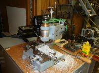
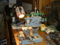
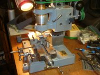
Many years ago I acquired a Derbyshire Micromill, for which I've been seeking a practical use.
Now I've hit upon one: Hobbing small gears such as the 48DP change gears used for instrument lathe threading attachments.

After much thought, I worked out a conservative method of dealing with the helix angle of the hob (which I already have !). I'll detach the column from the base, and add a pair of plates, one bolted to the base, the other fastened to the column, with the means to swivel about a vertical axis. I'll set the angle with a sine bar, and that will remain the same for all gears made with that hob.

The gear blank has to rotate by one tooth for each rotation of the hob. I'll use the "unattainable" 127-tooth gear as the ultimate example, as so many will go to any lengths to avoid getting or making one. There already has to be a right angle between the axes of the cutter and gear blank (ignoring the hob's helix angle for the purpose of this part of the discussion), and a worm gear fits this bill very nicely, as well as increasing the accuracy of the tooth spacings.

It appears that a 40-tooth worm gear and one-start worm will do for rotating the gear blank ... but only if the worm is rotated 40/127th of a revolution for each rotation of the hob. That demands a 40-tooth gear on the hob's spindle and a 127-tooth gear on the worm. I'll mount the 40-tooth gear right on the hob arbor (which will be an extended "blank" 8mm collet) and the 127-tooth gear on a carrier bolted in place of the spindle-elevating rack, which won't be needed once the hob's centerline has been set for the gear blank. A double-U-jointed drive shaft will connect the 127-tooth change gear to the worm on the blank's carrier. That will allow me to machine a gang of gear blanks all at once without affecting the gear-to-gear meshing.

This arrangement requires no changes to the table movements, which in the case of my Micromill consist of a screw-fed Y axis and a lever & cam fed X axis.

All of these changes are reversible.

I've done something like this with a Brown & Sharpe indexing head and even on an Atlas indexing head:

http://www.georgesbasement.com/ToolP...eIndexCenters/
http://www.georgesbasement.com/ToolP...dexingCenters/

At the bottom of my Atlas page there is a section on making 127 divisions without using a 127-tooth master. This Micromill project carries the concept one step farther.

Any and all comments are entirely welcome !

Best regards,
George

George Langford in SE PA
george (at) georgesbasement(dot) com
georgesbasement on Practical Machinist
 
Neat idea George,

I have an RJS mill similar in layout to the Derbyshire but slightly bigger. Your "pair of plates" idea would work for rotating the column of mine as well.

Have you thought about automating the hob/gear blank coordination? This fella assembled an Arduino-based fourth axis that seems to work well -

https://m.youtube.com/watch?v=fMY8zUs3bZI

Bob
 
Neat idea George,
Your "pair of plates" idea would work for rotating the column of mine as well.

Have you thought about automating the hob/gear blank coordination? T
Bob

After a little more thought, it occurs to me that I can simply build the helix-angle offset into the [quite substantial] key that aligns the column to the machine base. That would be a quick job with my South Bend shaper and the aforesaid sine bar.

Then it also came to me this morning that I have a four inch [Chinese} rotary table that would be easily adapted to rotate the gear blank on a vertical axis. It remains to be seen how accurate that rotary table is ...

Those two steps reduce the preparation tasks by a lot. Now it's just a matter of making the change-gear fixturing, a U-jointed drive shaft, and an arbor to fit the Micromill's 10mm WW spindle.

If I were going to make hundreds of gears, it might be worthwhile to spend a lot of time buying, assembling, programming ... but the original idea behind these projects was to build utility into a series of machines that would otherwise have gone into the scrap heap of history.

Recently I had to throw out several long runs of professional journals for lack of interest in preserving the printed works; I have no space after closing a business that thrived for over thirty years ... still have two storage lockers full of books and scientific equipment. I have more interest now in keeping the old machining methods alive.

George Langford
georgebasement
 
With regard to the mention of "the Micromill's 10mm WW spindle." Derbyshire used the term Magnus-Elect to describe their 10 mm collets. The name was originated by the American Watch Tool Co., where Derbyshire worked before starting his own lathe company. When AWT was dissolved, Derbyshire bought their watch lathe business, gaining ownership of the AWT trade names and designs, including the Magnus, Elect, and Webster-Whitcomb. WW is the common name for the AWT 8 mm collet. So there is no "10mm WW spindle."

I have two Micromills. Their cuteness exceeds their utility, but I did, after 30 years of keeping them on a shelf, get one running and made some parts on it. It had no spindle, so I adapted a Magnus BB lathe headstock and made it into a vertical mill. It was missing the cam table feed, so I made a screw feed for it. I made a riser for the column to get some headroom under the spindle nose. The motor is a Bodine brushless variable speed. The other mill is still on the shelf.

I have a number of Derbyshire and Levin watch lathe screw cutting attachments and some gear sets are incomplete. I have a plan, yet to be executed, to adapt my Hardinge bench mill indexing head to allow use of an existing gear, like the 127, as a master to mill a stack of blanks. Seems much simpler, almost boring by comparison, than making a hobbing machine.

Larry

Micromill vert 1.jpgMicromill vert 2.jpgMicromill vert 3.jpgMicromill vert 4.jpg
 
The links went 404 when I tried to follow them.

Internet paranoia is to blame:

Go to georgesbasement [dot] com and then tack on the following data, de-bfuscated (hopefully):

ToolProjectsByGL AtlasMMIndexingCenters
ToolProjectsByGL BrownAndSharpeIndexCenters

Add suitable operators until they open. There is only aitch tee emm ell there; no other coding. "divide by" come to mind.

Plain old navigation should also look. All the link are on the opening page.

George Langford
georgesbasement
 
With regard to the mention of "the Micromill's 10mm WW spindle." Derbyshire used the term Magnus-Elect to describe their 10 mm collets. The name was originated by the American Watch Tool Co., where Derbyshire worked before starting his own lathe company. When AWT was dissolved, Derbyshire bought their watch lathe business, gaining ownership of the AWT trade names and designs, including the Magnus, Elect, and Webster-Whitcomb. WW is the common name for the AWT 8 mm collet. So there is no "10mm WW spindle."

I have two Micromills. Their cuteness exceeds their utility, but I did, after 30 years of keeping them on a shelf, get one running and made some parts on it. It had no spindle, so I adapted a Magnus BB lathe headstock and made it into a vertical mill. It was missing the cam table feed, so I made a screw feed for it. I made a riser for the column to get some headroom under the spindle nose. The motor is a Bodine brushless variable speed. The other mill is still on the shelf.

I have a number of Derbyshire and Levin watch lathe screw cutting attachments and some gear sets are incomplete. I have a plan, yet to be executed, to adapt my Hardinge bench mill indexing head to allow use of an existing gear, like the 127, as a master to mill a stack of blanks. Seems much simpler, almost boring by comparison, than making a hobbing machine.

Larry


Thanks for correcting me regarding my overly generic usage of the term, "WW." I kinda like that 10mm buttress thread; I find them easier to make than to identify in sellers' pictures. I recently got a suitable tap, but haven't yet tried it out. I'll be using the tap to finish my own threaded holes to improve their surface finish.

My Micromill's longitudinal feed range is limited because the cam interferes with the underside of the table ... it rather looks like an afterthought, out of character with the rest of the mill.

I saw your post on the saga of the thread-cutting attachments - "still in print" so to speak, after decades (?) waiting for interested purchasers. I found mine (obtained from another source, but for almost as much money) rather easy to install, but it took me decades to get around to doing so. I had to retire first: ToolProjectsByGL DerbyshireLathe [after georgesbasement[dot]com and with suitable operators.]

Using a 127-tooth gear as a master is covered here: Goodell-PrattLathe GearCutting-7104RS[dot]jpg [as above] Later, I made the arrangement stiffer with a fatter spacer between the master and the blank. The arrangement shown vibrated too much. No less tedious than the usual method with a dividing head, as the two clamps had to be loosened and retightened after each tooth.

Your marriage of the Magnus headstock to the Micromill is very neat and robust. Did yours have the spring-loaded sliding portion of the spindle support or just the screw-fed downfeed ? Tony Griffith describes the feed range of the Micromill incorrectly - the cam-fed portion is indeed quite as short as he says, but the screw-fed portion is several inches more.

I once added a vertical mill adaptation to a Childs 0000 horizontal mill, based on a Unimat ball-bearing quill, with a fine down-feed arrangement that I designed myself. It's shown here: ToolProjectsByGL Childs0000UnimatHVMM [added to ... as above]. Unfortunately, even after tearing apart the mill's table and feed mechanisms, they are entirely too notchy and stiff to use the vertical head with a small milling cutter - there's no "feel" to the table's ball bearing feed mechanism. Another problem was drive belts - O-rings didn't work; recently, those green-plastic easily-resized round belts became available (to me at least) and I find them quite usable.

Many years ago I (literally) picked up a very early Hardinge horizontal bench mill at a New Hampshire tailgating session prior to one of Martin Donnelly's antique hand tools auctions. I carried it around, dangling from one hand, until I got it back to the car. I could have re-sold it several times during the walk. Now I think it might do better as the hobbing station, as it has no overarm support for the cutter arbor, but the 48DP hobbing cutter won't tax that arrangement at all. The head is detachable - held on by a pair of cams like a watchmaker's lathe headstock - but the tiny camlock spindle nose is a daunting thing to adapt to a home-made cutter arbor. It also accepts the 3C collet (Hardinge-made or South Bend made) and that is much easier to use as a pattern for a cutter arbor for the 48DP hob. All it needs now are a few small parts and the longitudinal table gib. Once those are made, the adaptation is no different and no more difficult than the Micromill's would be.

All the [great many !] gears that I have made in the last few years using existing gears as masters have meshed smoothly with each other and function well as change gears. What's nice in that process is that the master gear can be replicated in any pitch size for which you have a suitable set of cutters. On the other hand, you'd theoretically need eight cutters for each pitch, whereas one hob will do for any number of teeth, and [my 48DP hob, at least] costs a lot less than the set of eight involute gear cutters costs. Of course, to actually make a set of change gears with that hob, you need another set of change gears, not as masters, but to make up the gear train needed to rotate the blank for the gear being made. Still, there's only one set of change gears needed to make any other set of whatever pitch size is needed. See, for yet another example: SebastianTreadleLathe [with additions as above].

Best regards,
George Langford
georgesbaement
 
Then it also came to me this morning that I have a four inch [Chinese} rotary table that would be easily adapted to rotate the gear blank on a vertical axis. It remains to be seen how accurate that rotary table is ...
... Now it's just a matter of making the change-gear fixturing, a U-jointed drive shaft, and an arbor to fit the Micromill's 10mm WW spindle.


Upon further thought, a much more easily arranged scheme comes to mind: Place the small rotary table flat (with a suitable shim to set the helix angle associated with the hob) on the Micromill's table, drive the rotary table's worm through a constant-velocity universal joint (not Rzeppa, but double Cardan joint instead) inside a ball joint to maintain alignment. The CV's drive shaft will be driven by change gears fastened to the vertical slide. The change gears will mesh with a master gear (with the same number of teeth as the ratio of the rotary table) fastened to the spindle adjacent to its drive pulleys.

Now the set of gear blanks will be rotated about an almost-vertical axis, the feed of the hob will be downwards using the vertical slide of the Micromill, and the longitudinal feed and cross feed will be used to set the tooth depth and centering of the hob to the rotation axis of the gear blanks, respectively.

No modifications to the Micromill, except to change the drive pulley from two grooves to one. How is it fastened ? All I see is one tiny setscrew ... Will it slide off with my use of a gear puller ?
 
Upon further thought ... drive the rotary table's worm through a constant-velocity universal joint (not Rzeppa, but double Cardan joint instead) inside a ball joint to maintain alignment. The CV's drive shaft will be driven by change gears fastened to the vertical slide.
Time for eating my words. A quick search revealed that Rzeppa CV joints are made commercially for radio-controlled models of substantial motor output. I found them with 6mm drive shafts (0.236 inch); they're not cheap, but it doesn't take much to rotate my 100mm rotary table. Even double Cardan joints in that size range are made for such models, but they require alignment aids to get smooth operation, which are built into the model Rzeppa drive shafts. The Rzeppa model drive shafts even have sliding keyed joints, exactly what I need for the Micromill to accommodate the necessary down-feed motion of the hob.

I've even created a .DXF drawing and am waiting for a quote for laser-cutting the gear blanks from brass plate - about seventy pieces in a twelve inch square bass plate an eighth of an inch thick.

George Langford
georgesbasement
 
George,
Attached are some pics of a hobbing attachment I built from my small Burk horz mill. The hobb spindle is connected to the work via change gears, driveshaft and a 40:1 reduction box. It's a universal mill so the table can rotate to the correct angle. Whether you use a reduction box or dividing head there can be no slop. I had to make eccentric bushing for the box to remove the slop. You will need something on the order of 40:1 to make the change gears work.
Not sure how to make all of this work on a vertical mill.

Good Luck,

Joe

Gear Hobbing 013.jpgGear Hobbing 009.jpgGear Hobbing 007.jpg
 
George,
Attached are some pics of a hobbing attachment I built from my small Burk horz mill. The hobb spindle is connected to the work via change gears, driveshaft and a 40:1 reduction box. It's a universal mill so the table can rotate to the correct angle. Whether you use a reduction box or dividing head there can be no slop. I had to make eccentric bushing for the box to remove the slop. You will need something on the order of 40:1 to make the change gears work.

Good Luck,

Joe

That's a very clean arrangement. Your comment on the 40:1 ratio is more important than you imply. In order for the workpiece to advance one tooth for each rotation of the hob (assuming a one-start worm inside the reduction gearbox) the change gears have to be in the same ratio as the gearbox (or rotary table) in keeping with the number of teeth you want in the workpiece. For that 40:1 ratio, this works out very simply to a hob gear having 40 teeth driving the worm in the gearbox via a change gear having the same number of teeth as you want the workpiece to have ... and the workpiece diameter has to have a diameter derived from this formula: D = (N + 2)/P where N is the number of teeth and P is the diametrical pitch of the gear.

I took apart my little rotary table (marked "India" in stenciled paint) and found that the worm looks OK but it's driving a plain 36-tooth spur gear. Back to the drawing boards. Gotta find a real worm gear, whatever the number of teeth, as the change gears don't care how many teeth, so long as the ratio satisfies the simple requirements.

George Langford


Back
Top