What's new
What's new

Ingersoll-Rand Type 10 Compressor, or what?

Keelan

Hot Rolled
Joined
Jul 19, 2007
Location
Canada
8 years ago, my wife and I moved to Kelowna from an area east of here known as the 'Kootenays'. There's two Kootenays, East and West each with their own rich mining history. Metals (gold, silver, copper, lead, zinc) in the west, and Coal in the east. Except for the enormous open pit coal mines of the East Kootenays, most of the mines are a fading memory.

While trees make up most of the scenery of the 4 hour trip 'back home', there are a few little towns along the way. The one of interest to this post is the 'city' of Greenwood, population 656. This town is situated among the ruins of a copper smelter, the smoke stack and black tailings pile still play a very prominent role in the local scenery.

Sitting in a rough field in what I assume is a park, as there is playground equipment near by, are a few machines. After 8 years of driving by, I finally decided to stop and take a look:

P1100297.jpg


P1100299.jpg


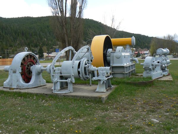
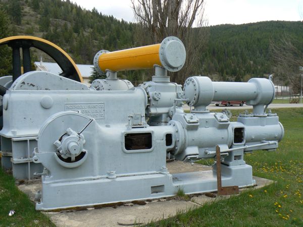
The larger machine is an Ingersoll Rand Type 10 compressor. I didn't think to take a photo of the other side of the smaller machine where the descriptive marks were. It is manufactured by Ingersoll Rand as well. From reading here, I see that the Type 10 is not a rare piece of machinery; in fact, our own Rick Rowlands has one in preservation.

I have a few questions:

1. Does the type 10 run on steam, or is it externally driven?

2. Somewhat related to the first question, why would a generator be belted to a compressor? The piece of electrical equipment is a Westinghouse 3 phase AC generator, 236 A, 440 V.

3. What is the smaller Ingersoll Rand machine? I'm assuming some sort of compressor as well...
 
There was PROBABLY...

There was PROBABLY a steam engine connected to that generator, probably in the middle of that double flange coupling... so that the engine ran at constant speed, the generator ran constant, and the compressor ran off that big flat-belt clutch.
 
It is possible to use an AC Generator as a synchronous motor. We used to occasionally "idle" the generators at Bellows Falls Hydro. Unit would spin and "motor" and this would provide VARS (volt-ampere-reactive) to the system depending on how the unit was excited.

Gotta balance those VARS. Keep the power factor up near unity!

I confess as a mechanical engineer, I'm a little weak in this theory area (intentionally!)

And this is slightly different than most central station generation which has "reverse power trips" to keep the generator from motoring. Don't want to heat up those last stage turbine blades any more than we have to.

Notice that the generator/motor has a small pulley on the outboard stub shaft. Probably drove a DC exciter through a wide leather belt which served to excite the generator.

Joe
 
A shop I used to work at had one of those horizontal single piston IR air compressors and it had a motor very similar to the one in your picture. The boss never used it since it required water cooling (which was missing)and he didn't want to mess with it. It ran just fine though.
 
That Imperial Type 10 is electric driven by a flat belt from the motor. The Type 10s were extremely versatile machines. This one is the simplest, just a compressor driven by an external power source. Other versions were self propelled using either two simple steam cylinders, cross compound steam cylinders or two internal combustion cylinders. In the self propelled versions the air cylinders would be located at the opposite end and the power cylinders placed where the air cylinders are on this version.

What I find interesting about this compressor is that the driving pulley is equipped with a clutch. Usually with an electric driven machine they would just stop/start the motor, but apparently the motor ran continuously and the clutch engaged or disengaged the driven
pulley.

We may someday get our Imperial Type 10 operating, but don't hold your breath. Its the lowest machine on our priority list.
 
Keelan:

As Rick Rowland has mentioned, the Imperial Type 10 came in several styles. The large
compressor is an XB-2 style, that means a belt driven, cross compound machine. Because
the intercooler is located on top, that would indicate that this compressor has a stroke
of 16 inches or greater and is a heavy duty pattern, which means a high pressure cylinder of 13 inches and a low pressure of 22 inches. Because the valves are the direct
lift type, it was probably built prior to 1915. While the discharge valves are of the direct lift type, the inlet valves (which are not visible in the photograph) are most likely of the mechanically operated Corliss type. The two bars on the stand in front of the driving pulley are for supporting the idler or jockey roller, used to increase the arc of contact of the belt on the flywheel. This type of compressor was designed to operate between
80lbs to 100lbs. with an operating speed of 170rpm. Assuming a stroke of 16 inches and
an hp bore of 13 inches and an lp bore of 22 inches, this compressor would deliever 1190
cubic feet of free air per minute at sea level. While delievering air at 100 psi would require
206 hp at the crankshaft.

The smaller compressor appears to have been built after 1915 and features Rogler valves.
This style of valve consist of a flat valve plate with concentric grooves milled through.
A thin valve disc with concentric grooves cut though and designed to cover the grooves
in the valve plate is held in position with a series of light springs. This type of valve
requires very little lift of the valve disc for maximum discharge and reduces wire drawing
to a minimum. The two flywheels are missing. Without the information on the other side
of the compressor, it is hard to tell exactly what model it is, but it appears to be very
similar to a model NE2-2 fitted with an overhead intercooler. These compressors were
designed for gas or gasoline extraction, but could be adapted for other uses. The stroke
was usually 6 inches to 8 inches with a maximum bore on the hp cylinder of 4 inches and
a maximum bore on the lp cylinder of 10-1/4 inches. One more thing, the flywheels on the
6 inch stroke compressors are 36 inches in diameter and on the 8 inch stroke compressors
are 45 inches in diameter. If you can furnish the missing information from the side of the compressor, I may be able to furnish further details.

Hendeyman
 
Here is a two cylinder Ingersoll Rand type 10 compressor I photographed a few weeks ago in Whangarei, NZ. It is arranged so it can be driven by a two cylinder Ruston diesel engine. Although both compressor and engine come from a limestone quarry, they were not originally paired. There was another engine at the museum (a single cylinder Tangye diesel of 94hp) which did once drive a compressor at a limestone quarry, perhaps this one. Unfortunately I didn't photograph the sign which gave the history of this compressor.


As featured in this recent thread:

http://www.practicalmachinist.com/vb/antique-machinery-history/o-t-some-fine-old-machinery-201403/index2.html
 
Thanks for all the detailed information, hendyman. Your explanation made a lot of sense out of the design for me. I wasn't understanding why the cylinders weren't identical.

I got in touch with someone from the Greenwood museum; all they could tell me was that the compressor came from this place:

Granby Consolidated Mining, Smelting and Power Company, Limited - Wikipedia, the free encyclopedia

And that it has been there since the 80's. You'd think they could at least put together some kind of descriptive something-or-another so that the equipment isn't just another giant paperweight. I'll be heading through the area again next weekend, I'll try and get a photo of the other side of both machines.

The generator is certainly an alternator and not a motor, says so right there on the name plate. Of course, I am in no position to rule out that they weren't up to something to make it operate in reverse, and given the way mines were run in the area, I wouldn't be surprised. Speaking of the area, one of the oldest continually operating power companies in Canada was formed in nearby Sandon, BC during the same boom:

SILVERSMITH POWER AND LIGHT CORPORATION

This plant was originally established to provide power to the Silversmith Mine in Sandon BC. From the same turbine, they turned a generator, and when needed, a big Ingersoll-Rand compressor that provided air to the underground workings of the mine. I plan on getting up into the area for a tour at some point in the near future.

This seems to be a theme for a few mines that once existed in the same area. The Silversmith is the only remaining operation, but a number of power & compressed air plants existed throughout the area to serve the needs of the mines with which they were associated.

Back to the Granby mine, I have found one photo online that shows that they had a hydroelectric plant, so I suppose there is a good chance that this compressor was in fact turned by water power.
 
The Granby Company seemed to operate large scale projects and since they were often in remote locations they built company towns and were self contained. Google "Anyox" and you will find a very large copper mine that operated between about 1900 to 1936 when it was closed. Power to run the smelters came from a hydro dam the Granby Company built and which still exists today. In fact there is a project underway to refurbish the dam and generate power under the BC Hydro entity.

Here is a link to a number of photos of the remains of mostly concrete structures after 74 years. This site does not contain any photos of the dam site, but they are elsewhere on the web.

Anyox Copper Smelter - Granby Bay - Observatory Inlet


Back
Top