What's new
What's new

Lathe in Service Since 1854 (1909 article)

Peter S

Diamond
Joined
May 6, 2002
Location
Auckland, New Zealand
In the recent "Lidgerwood" thread, Jim Christie used his great research skills to find an interesting article in the December 1909 Railway Master Mechanic Journal. It featured the Lidgerwood high speed cableways used to build the Gatun Locks on the Panama Canal.

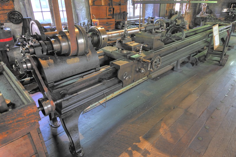
I looked at a few other pages of the same magazine and came across this rather attractive lathe from 1854, still in use in 1909. Does anyone recognise it?

BTW, the article was about electric drives for machine tools.

Railway master mechanic [microform]


lathe 1854 railway master mechanic Dec 1909 edit.jpg lathe 1854 railway master mechanic Dec 1909.jpg
 
The bed defiantly looks Putnam, I saw one a few months ago, disassembled, I beleive that one was a pattern makers lathe if I recall, bed was the same.
 
Putnam. One sitting in forlornly in my field right now...and another at the bottom of the hill in another field (that one's not mine).

How two of the same lathe ended up in nearly-nowhere-montana all of a mile apart is probably a tale.
 
The tail stock has been replaced.

My thought too. Probably broke the "ring pull up" on the original (a common failure and at least one reason square topped ring clamped tailstocks were obsoleted), and rather than re-make the ring they simply found another tailstock that worked. The tailstock looks like my Flather.

The rest of the lathe looks "early."

I like the apron gear - first of these I've seen on a Putnam.

"Keep your hands, head and arms inside the car at all times" era.

Joe in NH
 
cncfireman, Joe & others,

Do you think the external gear on the apron is an idler for driving the cross slide? I wonder if it is an afterthought by some clever user, or a hasty Mk 1 design effort by the makers. I suppose it might have once been guarded.

What is the big hole in the base of the tailstock, at 90 degrees to the ways?

edit: On 2nd thoughts, we might be looking at a stationary disc/guard on that big gear.
 
cncfireman, Joe & others,

Do you think the external gear on the apron is an idler for driving the cross slide? I wonder if it is an afterthought by some clever user, or a hasty Mk 1 design effort by the makers. I suppose it might have once been guarded.

What is the big hole in the base of the tailstock, at 90 degrees to the ways?

The "big hole" appears to not be a big hole, but rather a "dial" added to the tailstock lateral adjusting screws.

I have a Lathe & Morse lathe TAILSTOCK ONLY (also headstock) from an early 1870s era L & M (Bed scrapped by the scrapyard parts source) which has graduated "dials" placed on the two lateral screws. One supposes these screws gave indication of "set-over" of the tailstock for turning tapers. I can see this might be prone to some error but the dials MUST have been an aid at setup for taper otherwise why would they exist?

As to the gear - MANY "improvements" can be made to a standing machine. As I say, I have not seen that improvement on Putnam specifically, and like CNCFireman's example, on time-concurrent lathes.

Hagley Museum has an early large time concurrent Putnam SANS gear. But I can see how one might have been added.

5956526394_227ca5109c_b.jpg


Note that the Hagley lathe has raising blocks UNDER the headstock, and a raising block MIDWAY at the top-bottom lateral adjust slide area on the tailstock.

Joe in NH
 
The tailstock looks original to me.
What Joe calls the ring pull is still there. One of the ball knobs is broken off.
I don't know what is hanging on the tailstock adjusting screw, but it is not a dial.
You can see the center of the adjusting screw. Whatever is on it is hanging there.
You can see the center of it is below the center of the screw, so it would not be a dial.
It looks like it could be a spacer ring for the tool post.

Rob
 

Attachments

  • Putnam lathe 1 (2)_LI.jpg
    Putnam lathe 1 (2)_LI.jpg
    97.4 KB · Views: 109
Last edited:
Is this feature (see photo below) of any interest?

Auxiliary slide provided for turning of "larger" objects. A way to compensate for a limited application of the main (center) dovetail slide. This a design adaptation on steroids derived from the earlier concept three point support rise & fall rest - which can move the tool post ANYWHERE on the top of the cross slide "T."

On the original three point slide cuts at this position are necessarily light and tend to lift the rear of the weight restrained carriage. On this lathe the rear gibs on the carriage probably hold it down.

Were the 1909 picture better a matching female slide might be seen within reach of the operator. Or possibly the main slide can be moved to this position?

A Harrisburg, PA Craigslist lathe (Fitchburg) a couple of years ago embodied this feature. (pix below)

Peter (of this board) has a slightly newer similar Fitchburg Lathe with the same auxiliary slide on additional steroids. One can move the toolpost laterally on the auxiliary slide and get closer to the flexibility of the rise & fall - without the disadvantages.

Joe in NH
 

Attachments

  • 00F0F_fvIdhOJyzI3_600x450.jpg
    00F0F_fvIdhOJyzI3_600x450.jpg
    37.1 KB · Views: 83


Back
Top