Asquith
Diamond
- Joined
- Mar 3, 2005
- Location
- Somerset, UK
Did I mention that I'd been to London's Science Museum?
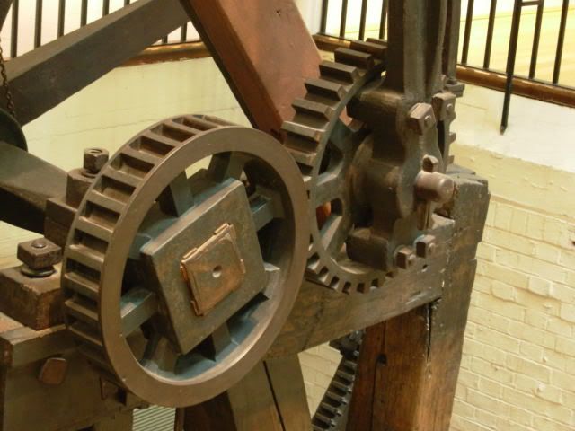
Boulton & Watt, 1788. Sun and planet drive invented to avoid infringing William Pickard’s patent on the conventional crank. Seems incredible that the crank was patentable, but those lawyers got everywhere, even then.
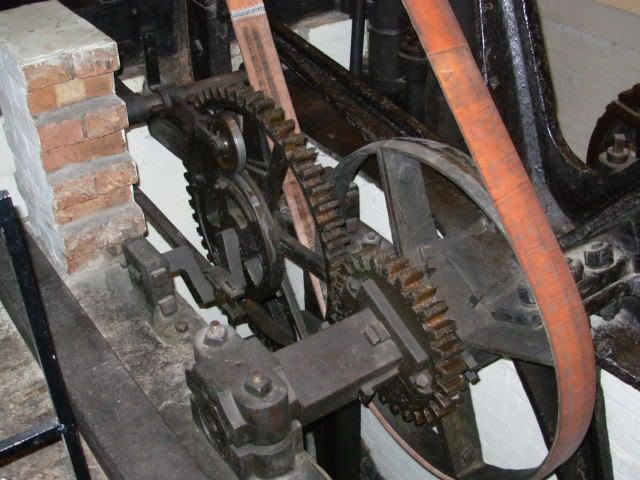
Boulton & Watt, 1797. Worked until 1885.
Note early use of roller cam follower! Thought not to be original, but possibly dating from when engine was uprated in 1806……….
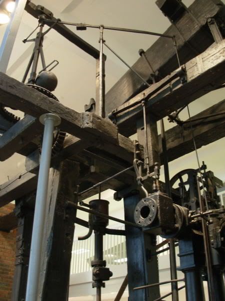
The cam operates rods and levers, and if there isn’t too much lost motion, it actuates the square-bodied valve (in photo above) to provide an early cut off of the steam and utilise its expansive properties. Note the plate-type spring above the valve. Immediately downstream of the cut-off valve is the throttle valve controlled by the flyball governor.
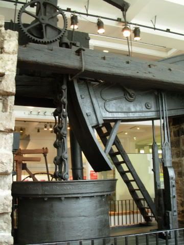
Beam engine built by Francis Thompson, 1791, for a colliery. The cast iron beam with the frivolous ornamentation was fitted later, when the engine was moved to another colliery.
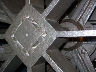
From the Cubist School of engine design.
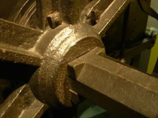
Triangular keys for an octagonal shaft.
Both the above photos were of a paddle steamer engine, I think.
There were a couple of model boilers that I wish I’d studied more closely:-
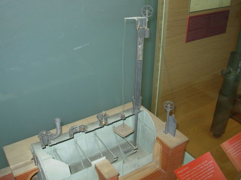
In this ‘Waggon’ type boiler, there’s no obvious way of knowing the water level, but there is a wooden float that opens a plug valve in the filler standpipe. Why, though, does the counterweight for the furnace damper live in the standpipe? It appears to made of lead, so it’s evidently not a float.
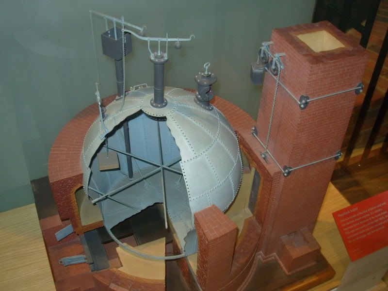
Lower pressure boiler, lower standpipe. The fire goes underneath and round the sides.
Chain on one end of the safety valve lever to allow it to be tested. Ample scope for putting extra weight on the other end drive the engine harder. This practice, together with bad design, poor workmanship, corrosion, low water level, etc., led to an early demise of many such boilers. How often did boilers blow up? Only once.
There’s an original version of one of these ‘haystack’ boilers on display with the 1791 beam engine, and also a nice old photo of one with a big opening in the side, with a horse emerging from it. Stable boiler conditions.
There’s an even older engine in the museum, a Watt beam engine dating from 1777, but it’s not much to look at. Originally an experimental engine nicknamed Beelzebub, it was tamed to pump water, and acquired the name Old Bess. The water was discharged to ….. the top of a water wheel. I don’t think that this was a means of avoiding the crank/flywheel problem, it just reflected fairly common practice for obtaining rotary motion.
Some of the engines had electric motors, but none of them were moving. Fortunately, if I want to see old engines running, in steam, I don’t have to travel far to the 1812 Crofton pumping engines.
Boulton & Watt, 1788. Sun and planet drive invented to avoid infringing William Pickard’s patent on the conventional crank. Seems incredible that the crank was patentable, but those lawyers got everywhere, even then.
Boulton & Watt, 1797. Worked until 1885.
Note early use of roller cam follower! Thought not to be original, but possibly dating from when engine was uprated in 1806……….
The cam operates rods and levers, and if there isn’t too much lost motion, it actuates the square-bodied valve (in photo above) to provide an early cut off of the steam and utilise its expansive properties. Note the plate-type spring above the valve. Immediately downstream of the cut-off valve is the throttle valve controlled by the flyball governor.
Beam engine built by Francis Thompson, 1791, for a colliery. The cast iron beam with the frivolous ornamentation was fitted later, when the engine was moved to another colliery.
From the Cubist School of engine design.
Triangular keys for an octagonal shaft.
Both the above photos were of a paddle steamer engine, I think.
There were a couple of model boilers that I wish I’d studied more closely:-
In this ‘Waggon’ type boiler, there’s no obvious way of knowing the water level, but there is a wooden float that opens a plug valve in the filler standpipe. Why, though, does the counterweight for the furnace damper live in the standpipe? It appears to made of lead, so it’s evidently not a float.
Lower pressure boiler, lower standpipe. The fire goes underneath and round the sides.
Chain on one end of the safety valve lever to allow it to be tested. Ample scope for putting extra weight on the other end drive the engine harder. This practice, together with bad design, poor workmanship, corrosion, low water level, etc., led to an early demise of many such boilers. How often did boilers blow up? Only once.
There’s an original version of one of these ‘haystack’ boilers on display with the 1791 beam engine, and also a nice old photo of one with a big opening in the side, with a horse emerging from it. Stable boiler conditions.
There’s an even older engine in the museum, a Watt beam engine dating from 1777, but it’s not much to look at. Originally an experimental engine nicknamed Beelzebub, it was tamed to pump water, and acquired the name Old Bess. The water was discharged to ….. the top of a water wheel. I don’t think that this was a means of avoiding the crank/flywheel problem, it just reflected fairly common practice for obtaining rotary motion.
Some of the engines had electric motors, but none of them were moving. Fortunately, if I want to see old engines running, in steam, I don’t have to travel far to the 1812 Crofton pumping engines.


