What's new
What's new

Old WMW BME 350 Lathe (1954) Reparation (Of Sorts)

Sidiox

Plastic
Joined
Aug 16, 2017
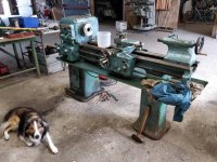
So recently I acquired an old Rambaudi V(R)2 Mill (of which I will make a separate post) and this rather ancient WMW East German lathe.
As a background, I am not a machinist, but IT student and know very little of metalworking (but do have basic workshop experience). All I know is via either YT or reading on the internet, so please forgive any mistakes I've made or will make whilst working on these machines. Or any jargon I may get wrong.

When I got the lathe it was in poor working order, missing the gears on the z feed (for the feed rod and thread rod)and covered in 50 years of thick grease and oil.
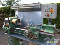
The electric motor has been remounted by someone who added an electrical panel on the backside, but the engine is on rather crooked. This combined with the poor bearings on the motor means it makes a lot of noise and does not run properly. So far I've replaced one of the bearings and about to replace the other. The crookedness of the motor is already fixed mostly, although the v belts do still have some flapping. (Its a 380V 3 Phase motor, of I think 3kw)

It currently runs and I am figuring out the controls. Due to someone repainting the machine with this weird blue/aqua color, not all the levers have their descriptions remaining (actually just the ones on the carriage).
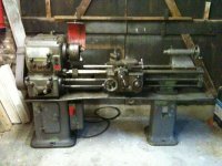
As you can see, so far I've figured out most of the controls, but am unclear as to what some of the handles do. The right most one of the z feed gearbox is seized currently.
The meanings of the two rows of numbers also isn't entirely clear, at least one seems to be the spindle speed as the lowest gear setting gives me about 50rpm.
The z feed gearbox is rather hard to open up (as far as I can see) so I haven't been able to see what the gears do.
I wonder if someone has any good idea on how to either figure out what they do or if they actually know how it works.

Lastly, I also don't quite understand the toolpost/toolholder. I haven't taken any proper pictures of it yet, but it looks like nothing I can find or the internet or properly understand by myself. The foot below the gearbox also lost a piece, but I may be able to weld it on, if the cast iron behaves.

I'll have to acquire an 160mm three jaw and some way to hold tools to start my first turning.

If I've made any mistakes by posting here, or if anyone wants to see something, I'm more than happy to comply.
 

Attachments

  • WMW BME 350 Lathe Carriage Side View.jpg
    WMW BME 350 Lathe Carriage Side View.jpg
    97.9 KB · Views: 647
  • WMW BME 350 Lathe Data Plate.jpg
    WMW BME 350 Lathe Data Plate.jpg
    101.1 KB · Views: 515
  • WMW BME 350 Lathe Full Corner Back View.jpg
    WMW BME 350 Lathe Full Corner Back View.jpg
    97.8 KB · Views: 818
  • WMW BME 350 Lathe Gear Box Controls.jpg
    WMW BME 350 Lathe Gear Box Controls.jpg
    97.1 KB · Views: 1,077
  • WMW BME 350 Lathe Gearbox.jpg
    WMW BME 350 Lathe Gearbox.jpg
    98.5 KB · Views: 692
Hi Sidiox, You don't mention the lever on top of the headstock. That and the two levers on the front of the headstock will be the three levers shown in the speed plate. Position them as to the positions on the plate and they will give you the range of speeds as shown.

On some feed boxes the levers are interlocked. You can only move one lever if the other lever is in a central neutral position.

The tool holder is just a simple clamp.

Regards Tyrone.
 
Oh yeah sorry, the lever at the top of the headstock is the one I refer to as 3 in my diagram.
And these three levers then correspond 2 numbers on the number row, which has me confused.

Regarding the toolholder, this doesn't seem to provide force to the backside of tools, seem rather weak, correct?

Thanks for the comment/help!

To me 3 ( or the lever at the bottom of the chart ) is the lever on top of the headstock. 1 and 2 are the levers on the front of the headstock.

It's an unusual tool post but I've seen tool posts on really big lathes were the tool is only held by clamping force.

Regards Tyrone.
 
Hi Sidiox,

I have te same lathe and refurbished it. I also live in The Netherlands. If you want you can take a look at it.
 
Sidox:

Welcome to our forum from the USA. We have members from all over, and we try to help each other as much as we can.

You have a good, basic and solid old lathe. In answer to your questions, there is normally a "chart" or "table" showing lever positions for cutting different threads and for the "Z" feeds as you call them. We call them "longitudinal feeds" or simply "power feed". The chart would have been fixed to the lathe above the quick change gearbox. This is the box with the spring-loaded lever which you can slide along and select a hole to lock the lever into.

The "chart" will tell you what positions of levers are needed to cut different pitches of threads, as well as the feed rate for the power feed to the carriage. This will be given in mm/revolution of the spindle on a metric lathe. The chart will also tell you what combination of gears to mount on the exposed gearing between the headstock and the quick change box to cut different threads. Typically, you mount one combination of gears to cut metric pitch threads, and another combination to cut "imperial" (threads per inch) pitch threads.

Possibly, Henky can get a picture of the "chart" showing quick change (also known as a "Norton" style gear change) and this will answer most of your questions.

Regarding toolpost or tool holders: As Tyrone notes, this is a simple clamping arrangement. It may not be too easy to use. Since you have a milling machine, you can make up the tooling you need. Getting some blocks of steel and milling slots for cutting tools and tapping for set screws ("grub" or clamping screws) to hold the cutting tools would be a way to get around the type of tool holder the lathe has. The steel blocks will allow you to use tools with common sized shanks or bodies, and will allow you to use the tool holder as it is. The only downside is you will need to mill the blocks so the tip or cutting edge of the tools is slightly below centerline of the spindle. You then use shims (packing pieces) to bring the tool cutting edge right up to the centerline. This lets you use a variety of tools, and if you grind your own from high speed steel blanks, you can adjust tool height accordingly.

Another alternative is to get a quick change toolpost such as "Aloris" or "Dorian" manufacture in the USA. There are plenty of lower priced Chinese made knockoffs of these toolposts. You may have to machine a new center stud to pass thru the body of the quick change toolpost, but it will give you a quick and easily usable system for mounting cutting tools in your lathe. I am sure other members will chime in about European quick change toolposts and tool holder systems.

The gears in the headstock look nice and crisp, no obvious damage. The lever on the headstock which you have labelled "Z feed clutch" may also be the feed reverse. This lever may have 3 positions: feed towards the headstock, neutral/disengaged, feed away from the headstock.

The levers with the question marks are used in conjunction with the "Z feed gears" lever to get the different threads and feeds. The lever you have labelled "Z feed gears" is known as the "tumbler lever". On some lathes it is also possible to disengage the lead screw (which you call the "threaded rod") so just the feed shaft rotates. The feed shaft rotates continuously whenever the feed gearing is engaged (lever up on the headstock). On most lathes of this type, the lead screw only rotates when needed for thread cutting, and has to be engaged either by a sliding gear or a lever which works a sliding gear. The lead screw on your lathe appears to have had a "shear pin". This is a soft steel pin of small diameter. It is designed to fail if the carriage runs into the headstock or if the lathe is overloaded. On your lathe, in the photo, someone has replaced the shear pin with what looks like a bent nail or piece of bent heavy wire (TIG welding rod ?). Aside from the bent end of this being a real safety hazard that can bite you, it is not healthy for the lathe, either. I'd check the hole to be sure it is clean and still round and not deformed from failures of this pin. Ream it to the next size using a hand reamer if this is the case, and fit a new pin. Make the pin from very low carbon steel, the softest steel you can get.

Getting the correct gearing for driving the "Z feed" will be your biggest challenge. Possibly Henky can supply numbers of teeth and diameters of these gears. In the USA, we buy stock gears from several manufacturers and bore the hubs to fit our needs if we cannot find used parts.

The lathe will give you a great practical education, and I am sure you will learn a great deal in repairing it as well as using it.
 
Hi,

I have added some before and after pictures of the lathe. I also tried to upload the manual (.pdf) but the file was to large to upload.

BR, Henky
 

Attachments

  • draaibank feb 2010 007.jpg
    draaibank feb 2010 007.jpg
    95.8 KB · Views: 493
  • IMG_0006.jpg
    IMG_0006.jpg
    95.2 KB · Views: 567
Hi,

I have added some before and after pictures of the lathe. I also tried to upload the manual (.pdf) but the file was to large to upload.

BR, Henky

You could do with different lighting I think. An open fluorescent tube will be easily broken and will probably be too bright and not localised enough. The light on the headstock will get in the way.

Nice job on the lathe though.

Regards Tyrone.
 
Sidox:
...

Thanks for your in depth reply! I've done some more work on it, it now has a proper 3 jaw chuck and I have some tools.
The main problem I have with the operation of the machine is that someone has painted it over completely. And I mean completely. They took the chart off and cut the labeling off and stuck it back on. The gearbox cover, the chip tray, the engine, everything looks quite horrible and is covered in this thick layer of green/blueish paint.

That's why the chart was confusion, someone must have cut off the labels, I couldn't tell what the rows were.
Using a little RPM meter I've now figured out how that works, with regards to the spindle speed.
Using the power feed will still require a lot of messing about, since as I said, nothing is labeled.
I have indeed found out how to switch between power feed and threading, however I don't know the ratio's and such yet (which is quite important....)
That'll just involve some measuring and messing about.

I may end up facing the clamp surface for the tool holder as it is in rather bad shape from more than half a century of use. I imagine if I properly mill it down I could even fit a quick change tool post. (Currently it wouldn't fit because the base of any tool holder would be almost above the spindle axle line).

Lastly, the gearbox may look good, but it's not entirely amazing. One of the gears makes a lot of noise and makes the motor run hot. The gear is held on with a little key on an axle and I *think* the key is kinda messed up. When feeling around, it has a lot of backlash and movement. It's also the gear that makes the machine run loud when engaged. I've tested this by just simply putting each gearset in neutral and listening/feeling when the noise/bad feel started.

However, I think I could replace the key and such (maybe....), but it require a lot of disassembling. I'll get around to it, but as a student, it'll take time. Currently I can use it for light turning in short periods of time. Which is quite enough for me I hope.

And indeed it has already learned me quite a lot, especially trying to work in the gearbox, figuring out how it works and where the noise came from.

Hi,

I have added some before and after pictures of the lathe. I also tried to upload the manual (.pdf) but the file was to large to upload.

BR, Henky

Wow, you did an amazing job on that machine! The manual would be amazing to have, as well pictures of the gear charts.
I don't know how feasible or useful it would be for me to visit you, but I'll send you a pm regardless.
 
Sidox:
...

Thanks for your in depth reply! I've done some more work on it, it now has a proper 3 jaw chuck and I have some tools.
The main problem I have with the operation of the machine is that someone has painted it over completely. And I mean completely. They took the chart off and cut the labeling off and stuck it back on. The gearbox cover, the chip tray, the engine, everything looks quite horrible and is covered in this thick layer of green/blueish paint.

That's why the chart was confusion, someone must have cut off the labels, I couldn't tell what the rows were.
Using a little RPM meter I've now figured out how that works, with regards to the spindle speed.
Using the power feed will still require a lot of messing about, since as I said, nothing is labeled.
I have indeed found out how to switch between power feed and threading, however I don't know the ratio's and such yet (which is quite important....)
That'll just involve some measuring and messing about. Also, I've replaced the bent pins/rods things from the z axles with properly fitting screws. They are not as soft/sheary as I'd like but a lot better than what they were (those things didn't fit properly in the holes and were almost catching on the machine itself...)

I may end up facing the clamp surface for the tool holder as it is in rather bad shape from more than half a century of use. I imagine if I properly mill it down I could even fit a quick change tool post. (Currently it wouldn't fit because the base of any tool holder would be almost above the spindle axle line).

Lastly, the gearbox may look good, but it's not entirely amazing. One of the gears makes a lot of noise and makes the motor run hot. The gear is held on with a little key on an axle and I *think* the key is kinda messed up. When feeling around, it has a lot of backlash and movement. It's also the gear that makes the machine run loud when engaged. I've tested this by just simply putting each gearset in neutral and listening/feeling when the noise/bad feel started.

However, I think I could replace the key and such (maybe....), but it require a lot of disassembling. I'll get around to it, but as a student, it'll take time. Currently I can use it for light turning in short periods of time. Which is quite enough for me I hope.

And indeed it has already learned me quite a lot, especially trying to work in the gearbox, figuring out how it works and where the noise came from.

Hi,

I have added some before and after pictures of the lathe. I also tried to upload the manual (.pdf) but the file was to large to upload.

BR, Henky

Wow, you did an amazing job on that machine! The manual would be amazing to have, as well pictures of the gear charts.
I don't know how feasible or useful it would be for me to visit you, but I'll send you a pm regardless.


Back
Top