conant
Stainless
- Joined
- May 13, 2013
- Location
- Shasta County, Ca. USA
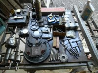
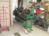
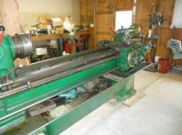
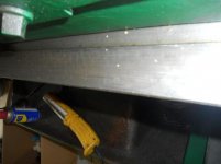
A few pictures from last month. I have been very busy with a away from home job and getting the lathe settled.
Follow along with the video below to see how to install our site as a web app on your home screen.
Note: This feature may not be available in some browsers.

From the pics it looks like it has a hardened bed, so scraping certainly wouldn't be needed. The ways look great though.If I ever actualy totaly need to go to a bed planing/scraping repair, I will do that.
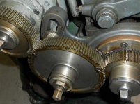
I believe every part on this machine can be dealt with for repair considering the fact it was never thrashed and has all the appearances of few operators. I base this fact on the lack of the usual crash marks/rubbing of jaws on the compound slide/hammer marks on machine or chucks/broken handles, gears or missing parts.
Even the tailstock quil taper is in fine shape.
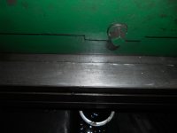
Repairs are pretty much: sight glass replacemant since it is hard to see much through the old plastic
All in all I am pleased.
I was going to buy Lexan and make a stand off washer type ring to duplicate what you describe. But a thought just sprung into mind: simply use an appropriate size O-Ring to do the same thing and seal at the same time. HMMMMMMMMMMM??????? I just talked myself into it.
Thanks for asking.
). If groove was cut into the glass, a slightly oversized o-ring would be great, and it would be easier to install without sliding.I was wondering myself if glass could be used with the extra gasket ring "stacked." It seams like glass would resist staining better than polycarbonate (although not bulletproof
Notice
This website or its third-party tools process personal data (e.g. browsing data or IP addresses) and use cookies or other identifiers, which are necessary for its functioning and required to achieve the purposes illustrated in the cookie policy. To learn more, please refer to the cookie policy. In case of sale of your personal information, you may opt out by sending us an email via our Contact Us page. To find out more about the categories of personal information collected and the purposes for which such information will be used, please refer to our privacy policy. You accept the use of cookies or other identifiers by closing or dismissing this notice, by scrolling this page, by clicking a link or button or by continuing to browse otherwise.