What's new
What's new

Steam Engine Flywheels

Peter S

Diamond
Joined
May 6, 2002
Location
Auckland, New Zealand
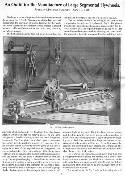
The recent thread about flywheel explosions set me looking at some articles, here is a photo showing the construction of a massive flywheel at the E.P. Allis Company. This photo is part of an article about flywheel manufacture that was published in American Machinist Magazine in 1900 and reprinted in a fairly recent Lindsay book "American Machinist Memories: Engines 1900-02"

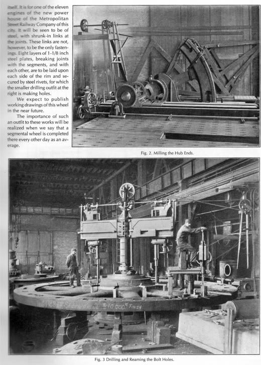
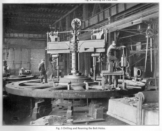
The flywheel is for one of the 11 engines being built for the new power house of the Metropolitan Street Railway Company in New York.

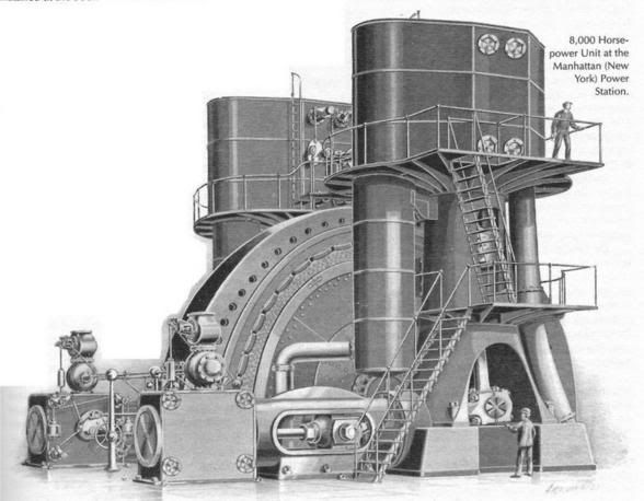
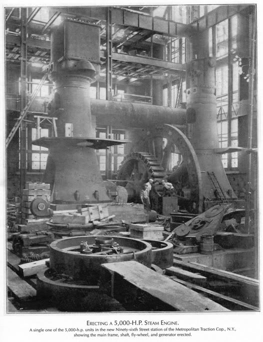
There are also photos of engines being installed at the 96th Street power house of the Metropolitan Traction Co. of NY, I am not sure if they are the same company and engines, though they look similar. They are 5000hp vertical cross-compounds generating electricity.

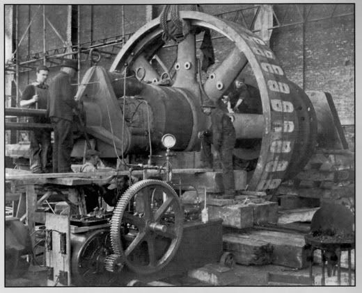
Anyway, here is one of the flywheels. Because of the tremendous power of the engine, and the particular danger that a generating engine has of overspeeding, it is made of cast steel, except for having a cast iron hub. It is 28' dia, weighs 310,000 lbs and is made in segments.

The man on the rim is drilling and reaming the holes which will be used to rivet on steel plates, 1-1/8" thick either side of the rim. These plates overlap the segment joints.
The article says that the works, on average, complete one segmental wheel every other day. An accompanying drawing shows that the spokes are hollow, but with a wall thickness of 3" in a radial cross-section.

Allisflywheelmanufdetail.jpg


This next photo just looked interesting - not exactly a flywheel, but the 'spider' for the generator, it fits alongside the flywheel (not yet fitted). They are using electric-driven hydraulic presses to fit the spider onto the shaft. (5000hp engine)

Allis5000hp96thstgenespider.jpg


And here is a photo of one of the engines in a more complete state.

Allis5000hp96thstassembly.jpg
 
The engines shown in the photos were known as "Manhattan Corliss" engines. I had heard tales from men who had worked on these engines in the IRT subway powerplant, and I had seen the building where they once stood. I think the building still stands and had become a base-load generating station for Consolidated Edison Company. The Manhattan corliss engines were riped out of there in the fifties to make way for modern steam turbo generating sets for AC power.

No less a person than Dave Sobel, the used machine tool dealer down in New Jersey, had worked in the powerplant with these Manhattan Corliss engines. Dave Sobel told me that he was working as a shift operator in that plant in the early 1950's. He said he used to get tired climbing the stairs and ladders up and down and around those engines making rounds. Dave also told me a hurricane struck the east coast, and the result was the lower elevations of that powerplant flooded. The power from that plant wasneeded on the IRT subways to keep things not only running but pumped out. Dave said the steam driven auxiliaries (circulating pumps, condensor wet air pumps, hotwell service pumps) all wound in or full under the water. Dave said most of that steam driven auxiliary machinery kept right on running despite the water. The babbitted bearings apparently did fine for a short runwith oil and water in them. I had only seen a few small pictures of the Manhattan Corliss engines in an old text, so seeing these photos was great.

I had the experience of putting together a few engine flywheels of varying sizes. I had put a few jointed flywheels together for stationary diesel engines. These were comparative pieces of cake as we had good rigging and these were smaller wheels.

The biggest of the sectioned flywheels I ever erected was on the Skinner Unaflow steam engine that went into a sawmill in Paraguay. That flywheel, while small when comapred with the 5000 HP Corliss generating engines shown in the photos, was fairly husky. If I remember right, that Unaflow flywheel went a little over 8 ft in diameter, and a face width of about 20" and went 8 1/2 tons. Skinner designed their flywheels to stay together, and the methods they used were kind of like the old guy who wore a belt and suspenders to make sure his pants stayed up.

Basically, Skinner's design called for casting the flywheels as one-piece castings. In the area where the segment joints were to happen, they put cores in the rim, creating pockets which were accessed from the inside of the rim. Along the edges of the rim, they put cores for rim keys or "dogbones". Also at the segment joints, the casting included massive flanges for studbolts to draw the joints together. As if all that were not enough, they made provisions for steel tie bars and wedge-keys to span each joint. Additional cored pockets in the rim were provided for the tie bars. Stud bolt holes were big enoguh to be cored.

The flywheel casting was poured as one piece. It was taken from the sand and machined. This consisted of putting undersized studs in all the flanged joints to hold things together and stable for the machining since the rim had those thn cored pockets With the wheel pulled together, it went onto a big vertical boring mill where the hub was bored and OD machined. The hub OD had to be machined for the admission valve eccentric and governor arm to pivot on. After the hub bore had the keyway put in, the rim had to be separated into segments. This was done by driving steel wedges in betwen the segment joint flanges at the cored pcokets from the inside of the rim. The wheel segments popped apart leaving unique "fracture joints" at each joint line.

Machining of the stud bolt holes, back spot-facing of the flanges to seat the nuts, machinign of the spokes where the inertia governor parts mounted, etc, all followed. There was a lot of machine work on the flywheels.

When I got the flywheel in the field, I had to get it together around the crankshaft. To do this, I had to deal with the engine foundation which had a kind of pit for the belly of the generator stator and for the flywheel as well as anchor bolts sticking up for the outboard crankshaft bearing. I took measurements and had the crew put timber blocking on the foundation and down in the wheel pit. We ultimately spanned the foundation with long timbers laid roughly parallel to the line of where the crankshaft would go. The flywheel half I had chosen to be the "bottom half" was laying out in the mud and weeds where it had been dragged off a flatbed rig sometime previous. We then got the flywheel half into the engine room by making a timber slideway topped with some steel plates. We got the wheel onto the slideway by dragging it close using a 'Cat. We then jacked the wheel half up and worked the timbers and slide plate under it. I had the crew smear grease on the face of the rim which was to slide on the steel plates. With comealongs, we then got the wheel half dragged along the plates and timbers so it laid flat, as if rotated 90 degrees to where it was going to go. Using the "A" frames and box girder we had made, we then picked up the flywheel half on chainfalls so it started off roughly flat. Out came the timbers. Using two chainfalls, we were then able to raise the hub side of that wheel half and lower the rim, letting the wheel down half down into the pit.

I had been explicit in telling the mill owners I wanted them to buy me wire rope slings made up with hand-spliced eyes. I wanted the hand spliced eyes on the slings so that when we went to turn or flip engine castings, they would not "catch" or "pop" over "sedged socket" type splices in the slings. This was 1981, so modern fabric slings were not in widespread use. In any case, the mill owners claimed they couldn;t get the good slings- although they had a purchasing agent in the USA. Instead, they furnished "swedged socket" type wire rope slings, not enoguh of them and some kind of short for the work. As we righted the flywheel half, as if we didn't have enough going on, we had to worry about the edges of the casting jumping off the swedge sockets on the slings holding it up. That made the rigging sing a bit and made the box girder vibrate some.

Next, the crankshaft went in. This was where the 100 ton P & H crane was brought on site. The crankshaft with the generator field on it was landed on cribs built of timber. This supported the crankshaft and got it high enough that we could refinish the main journals- which had been chewed up badly, rusted, damaged in shipping and then rusted some more. Refinishing the main journals (one being 14" diameter) took us a ful two weeks using mainly hand methods. While the P &H crane was on site, we had the uper half of the flywheel walked into the engine room and positioned up on cribbing above the crankshaft. we guyed it off with comealongs and wire rope to allow us to work on the crankshaft.

After we had the crankshaft to where I was comfortable with the journals, we jacked it down into the frame, leaving room for the main bearing quarters to come later. This left room to manuver the flywheel halves.

Before setting the upper half of the flywheel, we had to get things ready. Skinner used a mess of studbolts to draw the hub and the rims together. these were about 2 1/4" diameter or a little bigger and had fine pitch threads. Naturally, some fo the threads had been galled or damaged when the studs were removed. No rechasing dies, just files. A group of the crew sat on the floor and dressed up studbolt threads so all the nuts ran on and off nicely. The studs had to go in at a "black heat"- just shy of a red heat in the "stress zone". I welded some 1" steel washers to the ends of the studs to give us a place to handle them. Simiarly, the "dogbones"- the rim keys- had to go in at a black heat and were to be driven into the pockets in the rim.

We got ready by digging a pit outside the engine room and building a wood fire to heat the rim keys. The rim keys were tapped for eyebolts to handle them. We laid up firebrick dry and got the forge blower to blow a charcoal fire for heating the rim and hub studs. The dogbones went into the firepit late in the afternoon of the day ahead and soaked in the coals. We hung a few rope blocks and handlines with large hooks for handling the studs into the rim and hub. We go the 16 lb sledges and the slug wrenches ready as well.

I personally cleaned and inspected the "fracture joints" at the rim sections. I wire brushed and blew them clean and looked at them under good light. Lastly, I put an oil can with kerosene nearby.

On the big day for marrying the flywheel halves, we had rigged the top half so it sat with the key in the keyway at about 12:00. We had drifted the lower half so it was right under it. The lower half sat on timber blocking down in the pit. I had put a 10 ton porta-power jack down in the pit, so it hit the rim at 6:00. The last bit of the rasing of the bottom half was going to be done by the porta power jack. We jacked to where I could start the nuts on the studs. I had held some of the studs out of the fire to act as guides. We started by putting four studs in cold and loose into the rim joints and hub. I carefully put a few drops of the kerosene at the inside/center edge of each of the fracture joint. Then, we jacked up the flyhweel half and kept taking up on the studs serving as guides. When we had these bolts drawn snug, it was time to put in the heated studs. We got on some welding jackets and welding gloves and went at it. I had forged a couple of special bars for handling the studs- one being a "carrying bar" with a kind of dip in the middle so two guys could carry the hot studs without it sliding on the bar. The other bar had a kind of hooked end for handling the studs into their holes. This bar was used in conjuntion with wood blocking to prop up the fulcrum point as the bolts were heavy. I had the threads coated with a paste of steam cylinder oil and graphite, and the top nuts run on ahead of time. With the heat int he bolt shanks, the cylinder oil and graphite were running and smoking. We had a pattern to put the bolts in to try to keep an even strain on things, so began puting in the hot bolts. I ran up the nuts and washers from the bottom and we went like madmen. The idea was to get all the bolts in on a given joint and get the nuts run down and snugged while the shanks were still hot. Then, we ran around with two sets of slug wrenches and sledges, slugging up opposite corners on the flywheel. We had to do it all in one go and do it fast. I went by the old "ring of the wrench" method to know when we had enough "stretch" in the rim and hub studs.

After the studs were slugged up tight, we took a breather to let them cool and draw the wheel section joints a bit tighter. The next push was to get the dogbones into the edges of the rim. We pulled them from the fire with a chain on the frnt end loader and walked them on the loader thru a hole in the engine room wall. They were then transferred to the rope falls and picked to near where they needed to go into the rim. Bars threaded into the tappings on the "dogbones" let us lever and guide the dogbones to where they started into the rim pockets. SOme quick work with the 16 lb sledges and we had the rim keys driven home.

It had been a hard pull for us and we were sweated up, covered with soot from the fires and from the cylinder oil and graphite. I took a look at the half joints on the outer circumference of the rim. Kerosene was bleeding out. We had put a death grip onto the flywheel to joint it together. The only remaining work was to drive some relatively small wedge keys thru the steel tie bars. Why Skinner went to that length,I never found out. We drove the wedge keys home thru the inner rim, thru the tie bars and into the outer rim.

The flywheel was together and on its crankshaft. During the job, some of the crew's wives had brought us cow-horns or jars of cold herb tea called "yerba". It is traditional in Paraguay and is sucked up thru a straw made of plated brass tubing. We had all passed the yerba around, drinking off the same straws as we worked thru that flywheel. None of us seemed to worry about catching anything contagious. We were putting a flywheel together, and we had to do it fast and hard. Now, with the kerosene being proof positive the wheel was together solidly and truly, I had liters of cold beer handed out. We sat in the engine room and drank that nice cold beer, too tired to move for a bit. The head man and a lot of other people walked the few kilometers up from the nearby village to see the wheel together. The flywheel was together and on its crankshaft, and the crankshaft was up on timber cribs. More hard work would follow before that engine rolled. Everyone knew it, but seeing that flywheel together- after it had laid in pieces in the mud for a few years- was a special event. The Skinner Unaflow engine did roll and went on to power the sawmill. It pulled load and got slugged with loads when the sawyers on the two headrigs nailed into the cuts simultaneously. Coming out of the cuts and off load, the engine ran smoothly with no racing and no knocking or pounding. The frequency and voltage meters barely showed a twitch when this sort of sudden load changes occurred. It was a tribute to that big flywheel and to the good inertia governor.
 
Joe can you give us an idea of how long this took..... from the time you started to move the wheel from the weeds till beer time? Also like the pictures above....... and this I don't have a clue.... but would one assume that a small engine would be assembled and test run at the factory before being shipped.... but would an engine the size of the one pictured be tested before shipping or would it be erected for the first time on site? The real question is... how big do they have to be before you can't put them together in the shop? Thanks
 
Rivett:

The time frame for the assembly of that flywheel occurred over probably two weeks as most of the other engine and boiler work was going on at the same time. The flywheel halves had lain in the weeds for a couple of years before I showed up. The rigging of the flywheel halves into the wheel pit and up above the crankshaft took a few days prior to the actual joing of the flywheel halves. The day we put the studbolts, dogbones and tie bars in was probably a 12 to 14 hour day. This is what we normally worked for 6 days a week. The previous day to the actual joining of the flywheel halves, we got the pit fire going and burned down and put the dogbones into the coals. We also got the firebrick laid up and the blower in place for heating the studbolts. On the morning of the day we were to marry the flywheelhavles together, we probably had breakfast somewhere around 6 AM and were in the engine room by 7 AM. I do not recall that we stopped for lunch on that day. What I do remember was the men's wives knew something big was going on, so they came to the sawmill and into the engine room as the day progressed. Some brought food. The cow horns and jars of Yerba were passed around the crew without anyone breaking stride. I was in there with the crew, and spent part of the day inside the rim of the flywheel. The heated studs would be lugged into the engine room, transferred to a rope fall and raised up then swung into the flywheel. I was inside the rim of the flywheel, and would guide the heated studbolt into its hole. Another guy, working from the opposite side of the wheel spokes, would dope the threads with cylinder oil/graphite and then get the nut and washer on the bottom end of the stud. We would then put the wrenches to it and run things up snug. It's hard to describe how fast this was happening. My Spanish was minimal at best and the crew spoke Guarani (an indigenous dialect) and only some Spanish. Some which way, we had it happening. No one got hurt or worse and the wheel went together. We worked pretty near at a dead run once the bolts started getting pulled out of the fire. I am guesing it was around 7 Pm or a little later when we finally got to the beer.
It was a walk of perhaps 1/4 mile from the engine room up to the bunkhouse. It seemed like when the wheel was together, we all just sat there, holding our beers and no one saying a word. I remember the quiet, hearing sounds I hadn't heard all day- the lowing of cattle and songbirds. I really do not know how long we sat there with our beers before anyone felt up to joking let alone walking home to the village or up to the bunkhouse. I know the sun was low when we walked up to the bunkhouse, and the cook had waited on cooking supper until she knew we were done.

The time frame for the erecting of the entire engine and boilers as well as all the piping was ninety days from the time I came on site. The starting point was the foundations were done, engine manframe was up ont he foundation, although not levelled or grouted. The three boilers were hung on support steel, but no brickwork had been started. Absolutely no piping had been run.

In answer to your question of how big a flywheel had to be before it became a sectionalized thing:
There were a few determining factors. The first would be the diameter of the wheel. Anyhting over about 5 or 6 feet would almost have to be a sectionalized wheel for transport. It was a question of road clearance in an era before specialized tractor-trailers. It was also a question of weight to be handled in an era before mobile cranes were commonplace. It was also a question of what type of engine the wheel was going on. A bigger flywheel simply could not be transported assembled on the engine because it hung below the level of the engine frame. Some of the smaller engines like the little enclosed high speed engines (say about a 5" x 6" or thereabouts) might be shipped with the flywheels on them.

Transporting an engine with the flywheel on could also damage the babbitted bearings. On smaller engines, as on steam turbines and other machinery, if you have a heavy rotating mass on a shaft, it is good practice to jack up or block the shaft to take the weight off the bearings in transit.

A sectionalized flywheel made life easier for a lot of people, starting with the patternmakers. The Skinner engines used a one-piece casting which was broken apart to sectionalize it. I think an 8 or 10 foot diameter flywheel might have been the upper limit for this type of construction. An 8 to 10 foot flywheel could be made to break into two halves. Getting a bigger wheel to break on the quarters was possible, but I do not think it was done often. Instead, the bigger flywheels had machined faces at the section joints. The biggest flywheels had rim sections and individual spokes that also bolted in with fitted bolts.

In answer to your question about erecting in the shop: In the era the Manhattan Corliss Engines were built, this was a common practice. This was an era when things were built on manual machine tools and the predominant method of constructing machinery used massive castings. If a firm didn't do a trial assembly on the erecting floor, they took a heck of a risk in the field. In the era of iron castings, there was very little room for a field modification or fix. No handy-dandy portable electric tools, no plasma or arc gouges (can;t cut iron with oxyacetylene), no welding to speak of... Most of the engine builders had erecting floors with cast iron platens in the floors. These platens had tapped holes and tee slots and were machined and levelled on deep foundations. The steam engiens would be erected fully on the floor and often tried on steam. Skinner did load tests and running-in on their biggest engines right on the factory floor, as did Nordberg and a number of the other well known steam engine builders.

An engine the size of the Manhattan Corliss would have been partially assembled on the erecting floor to make sure everything lined up. The flywheel was too big and with shrink-fitted rim keys and studs, there was no point in assembling the flywheel only to knock it down again. The flywheel had been together on the boring mill, os it was known that it DID assemble.

I am sure the bulk of the Manhattan Corliss went together on E.P. Allis' erecting floor and the major pieces were then match-marked and dowelled. There was a practical limit to how far the assembly of an engine of the size of the Manhattan Corliss on the shop floor would have gone.

On a big horizontal engine, especially one like the Manhattan Corliss, the weight of the generator armature (this was a DC generator) and flywheel was going to put a fair amount of deflection into the crankshaft. As a result, the main journals were not going to lay flat on the main bearings. The mains would have been babbitted and bored, but still needed to be scraped in. Engines like the Skinner Unaflows had the main bearings scraped in at the factory during assembly. As long as the field erector got the mainframe and outboard bearing levelled and aligned, the bearings would be good. Something like the Manhattan Corliss was too big to assemble completely, so I am sure the erecting crew was scraping in the main bearings at the jobsite. I am also sure the erectors had stretched the "tight wires" (piano wires) thru the cylinder bores, bucked them to center in the cylinders and "built off the wires"- both on the shop floor and again at the powerplant installation site.
 
In pic #2, the electric motor, turning larger gear(hyd Pump)supplied the pressure to assemble things
The book is a good read, several things of interest.
 
Joe,
Great to hear more about the Skinner engine job, thanks.

The engines above are not the Manhattan type however. These ones are definitely just verticals, not the Manhattan layout.

Wow, you met a guy who saw the Manhattans running! If we are allowed to have engines as heros, these would probably be mine! ...I must try and contact Dave Sobel.

The 11 vertical engines above were built in the late 1890's for the 96th Street power plant of the Metropolitan Street Railway Co in NY City. They were 46" & 86" bore x 60" stroke, could develop 5,500 hp and generated ac at 6000 volts to power street cars (replacing horsecars and cablecars).
The same company had other power houses too, eg the 146th Street Power House picture shows a row of horizontal cross-compounds by E.P. Allis Co., 3 x 1,200hp, 2 x 600 hp.

By 1899 the not very old elevated railroad in NY was thinking of electifying (imagine the grime which came down from all those steam locomotives).

When Edwin Reynolds left the E.P.Allis plant in Milwaukee on a train bound for NY, he was thinking hard. The owners of the "el" wanted to generate 96,000 hp on one block of land. The existing designs of vertical cross compounds just weren't going to do it. His main problem seemed to be the huge weight of flywheel he would require for this type of engine.
There was more than just the engines to fit into that block of land, there were also boilers, chimneys, coal handling, auxiliaries, switchboards and future expansion to consider.

The idea of building a compound engine with one cylinder at 90 degrees to the other had been tried. (ie one cylinder vertical, the other horizontal).
However, Reynolds then considered duplicating this on the other side of the flywheel, thus having a double compound engine - much less space than a horizontal, but with still only two cranks and two bearings. The massive LPs could be placed vertically, as worked so well on the existing vertical engines.
Only one problem remained - the flywheel weight required was still too great. The solution was in deciding at what angle the two crank pins should be to one another. By placing the crank pins at an angle of 135*, the effect was to spread the eight power strokes evenly about one revolution of the crankshaft. The torque would be smoothed out to such an extent that no flywheel would be required, other than the revolving fields of the generator. (Note how the vertical engines in the photos above had a massive flywheel alongside the generator). No flywheel ment a lighter crankshaft, smaller bearings, less foundations and less space.

Further, these engines could never be caught on dead centre, and usually no barring was needed prior to starting.

Edwin Reynolds had the basic design and dimensions noted down by the time his train arrived in New York. The el was convinced and awarded E.P. Allis a contract for $3,000,000 worth of engines which had never been built or tested.

These engines were placed in Manhattan at 74th Street and on the East river. Thus this type of engine became known as the Manhattan. There were 8 engines in this power house, completed by 1903. Cylinders were (2) 44" & 88" x 60", turning at 75 rpm, steam at 150 psi and generating 8,000 hp at 1/6 cutoff on the HP cylinders (normal load) and 12,000 hp at maximum overload. Corliss valves on all cylinders.

The 74th Street plant displaced about 225 steam locomotives which during 1900 burned 227,000 tons of coal.

The Interborough Rapid Transit Co. was building a new subway line at this time, and also needed electricity.

A near duplicate of the 74th Street plant was built, this new power station was built at 58th Street and 11th Avenue. Completed by 1905 with 9 "Manhattan" engines. Only slight differences - (2) 42" x 86" x 60", turning 75 rpm, steam at 175 psi, 7,500 hp at normal conditions, 12,000 hp flat out. Poppet valves on the HP, Corliss on the LP. Each generator produced 5,000 kw of 3 phase ac at 11,000 volts, 25 cycles.

As part of the original installation, and pointing towards the future, there were steam turbines placed between some of the engines to provide power for the subway lighting system. These great mastodons of the reciprocating age of steam were still on standby duty in 1954 (all 9 engines), but were all scrapped (both plants).

Edwin Reynolds retired in 1905, and died 4 years later.

There are some excellent photos and details of these engines in the two volumes published by the ISSES - "Corliss man and Engines" by William D. Sawyer, from where I got most of the above information.

I will try scanning some of the photos one day.

Here is one to go on with... this looks like an engine from the 74th Street plant, has Corliss valves on the HP cylinders

AllisManhattan.jpg
 
Back to flywheels....Here is an article about manufacturing the flywheels seen in the first post.
(Thanks to Mr Lindsay, I hope he considers this as advertising for his excellent books, for those who have read his catalogues and seen his website, I wouldn't like to offend him
)

Allisflywheelmanuf01.jpg


Allisflywheelmanuf02.jpg
 
If anyone wants to get in on the ground floor of a project assembling one of these engines over the next year or so we will be assembling the 500,000+ lb. William Tod cross compound steam engine in Youngstown. I'm hoping that I can maybe recruit Joe to come out and show me how to line up the bedplates and cylinders. Other work we'll be doing include assembling the 20' flywheel including setting the shrink links (dog bones) assembling all the parts, cleaning and painting. Its probably the last time a flywheeled engine of this size will be assembled anywhere. Tod Engine Foundation Web Site
 
Edwin Reynolds left Allis at some point and went to work for the William Tod Co. and apparently brought his triple expansion water pumping engine design with him. The Tod pumping engines were referred to as Reynold engines.
pump.jpg
 
Rick,

I only have a brief history of Edwin Reynolds, and it doesn't say he worked at William Tod, but it doesn't mean he didn't act as a consultant, perhaps?
Also, I am guessing that his name became linked because of the patents he had, just as many engines had "Corliss" attached to them??

His brief history seems to be that he worked for 16 years at various jobs that gave him good experience in machining, building and superintending everything to do with steam engines (including helping John Ericsson to build the Monitor).

This led him to the Corliss Engine Works in 1867, where he became general superintendent of the works in 1871. Here, he patented his trip gear.

In 1877 he left what was one of the best engineering works and went to a lower paying job with the struggling E.P. Allis. They employed 150 men in poor facilities. However, his job gave him responsibility for all engineering and manufacturing, and Allis, with his management skills, gave Reynolds the freedom he needed.

The Reynolds-Corliss engine offered an improvement on the Corliss trip gear, it could run faster and allowed the engine to be governed better. The Reynolds engines sold by Allis were a huge sucess, thousands were sold.

Reynolds became a consulting engineer for Allis-Chalmers (formed 1901), but suffered from ill health and retired in 1906, three years before his death.

(edit note, some changes)

[ 05-21-2005, 06:59 AM: Message edited by: Peter S ]
 
When I was at the Library of Congress last year I found a blurb in the Iron Trade Review that mentioned that Mr. Reynolds left Allis Chalmers and went to the William Tod Co. I tried to find the copy that I made of the article this morning but naturally couldn't find it. When I do I'll post it.

Click on the link to see a pic of cooperation between competitors Allis Chalmers and the William Tod Co.! Allis Chalmers and Tod Engine


Back
Top