What's new
What's new

A visit to David Wilkinson's machine shop 1790-1840

G&L4nahalf

Cast Iron
Joined
Jul 27, 2014
Location
Temporarily Florida
Greetings PMers

Well I finally got to do it. Visit David Wilkinson's machine shop, very plausibly reconstituted from his time period 1790 to ~1840. It is formally known as the Wilkinson Mill Museum. Before I left to visit it, I could find very little about the machine shop posted on PM. I also visited the American Precision Museum in Windsor Vt, and the Ford in Detroit.

David's shop is located just a few streets from Interstate 95, in Pawtucket Rhode Island, a part of Providence. Anyone planning to go, be prepared to use GPS to find it, because the simple sounding directions from the official Inet site are not simple, except maybe for the locals.

Some time before I left Florida, I made special arrangements with the museum to extensively measure and photograph the machinery. Which request they most generously granted, and on Sat May 27th 2017, we were treated to an extensive after hours private tour with the machinery under power.. I have very many pictures that I would like to include in this thread, along with much measurements of some of the machinery, and much information.

The water-wheel power has been very faithfully reconstructed from the ancient drawings, and is an under-shot putting out better than 30 raw hp to the belting to the machinery. It is complete including a governor. It makes the building thunder. I have a number of good pictures plus some short movies showing the wheel in action.

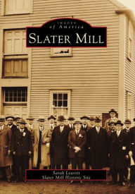
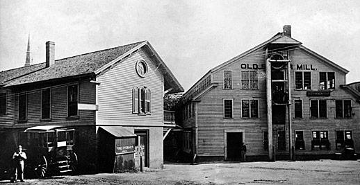
David Wilkinson Mill, Pawtucket RI 101_0081.jpg


David Wilkinson's water-wheel
101_0074.jpg

A small part of the shop
101_0052.jpg

My baby ... She is 124 1/4" long, 22" wide, and 48" to the top of the head-stock pulley. The large hand-wheel used to push the tool carriage toward the tail-stock via an internal toothed rack (not room to attach it where she's positioned because at the end of the feed stroke the rack extends quite a bit out of the front of the Engine Lathe) is 22 3/4" dia and covered with a 3/8" thick leather band nailed to the outer part of the wooden part of the wheel. I have seen some 100 year old leather in my time, but this is at least twice as ancient as what I've seen. I have a number of additional high-def pictures taken from different angles, including inside the wooden bed. She has to be the oldest known engine-lathe in the USA, and I would like to date her to about 1798-1799.
101_0017.jpg

Words cannot adequately express my thanks and gratitude to the staff of the Wilkinson Museum complex, and most especially Carl Johnson, the resident engineer-curator; who has made all this possible. But a heart-felt thank you, Carl.

PMers enjoy, and I hope I will be allowed to present much more, George
 
Some examples of the Line Shafting and wood-working

Even from the beginnings of his shop, David did much if not most of his work for his brother-in-law; who was the historically famous Samuel Slater with his textile mill nearby. Since most of the machinery in Slater's Textile Mill was wood construction with minimal iron work, young Davie did a lot of wood working; much on the same machines that were designed for machining metal.
101_0053.jpg


101_0033.jpg A large wooden planer, presumably used for planing wooden beams for the Slater Mill textile machinery. It seems that there was cross-fertilization of concepts and features between the wood planers and metal planers during this time period. On the right across from my measuring instruments on the floor, is one of the museums prize possessions;
a cylindrical drum sander in the small wooden bench, directly behind the machine in the right foreground.

I really have to admire the lantern hanging next to the modern electric light on the ceiling. On the far left wall hangs a bin cabinet for tools etc. Much much interesting stuff in these photographs. This museum has to be the premier in the USA for having the oldest antique machinery.


101_0051.jpg A little fun at this place, playing with the belts while trying to get your work done..

I'll try to put a lot more up as I can.

George
 

Attachments

  • 101_0050.jpg
    101_0050.jpg
    99.3 KB · Views: 669
Very interesting George. 30 HP from the undershot wheel, wow, no head needed to speed up the flow? That would be considered an impressive amount of power in those day I suppose, every detail involved a lot of personal thought, by which I mean that today we buy a lot of our engineering off the shelf, they had to think it through before starting.

For instance, a metal lathe, even if one had the concept already you couldn't just buy one, you had to design it. And that goes for probably 90% of the tools they used I expect.
 
George,
Thanks for taking the time to share the pictures and notes about your visit to the mill and for posting the picture of the Daniel’s type planer .
My edition of this book has a drawing of one to go with the description but I don’t ever remember seeing even a picture of an existing machine .
Internet Archive: Error
I was able to find more about them here .
US Patent: X8,548 - Daniels planer

Thomas E. Daniels - History | VintageMachinery.org

Regards,
Jim

I have been to the Wilkinson Mill twice and it is a treasure. I am pretty sure I have also seen that type of planer at the Maine Maritime Museum in Bath. I think it was in a separate building devoted to ship building. The Henry Ford has one of those planers in the main museum.

Larry
 
typical look of museums on how they preserve items.

However a few shots of oil on the rusting equipment would be a good idea one would think?

although nice to see a picture of something so old.

I think if you gave visitors a oil can they would happily lube things up while they are looking around.
 
My visit to the Henry Ford Museum some 60 years ago lit the fire in me that still burns, (Just as bright, not quite so hot these days!) I knew that I had to have my own shop, and a long list of projects began. Regards, Clark
 
The origen of the museum collection

Wonderful--I never knew this museum existed but will take it in on my next visit to see my son. Any input on how/when these machines were acquired? Were they original to this shop?

Tom B.

Thanks for your compliment Tom.

I think nothing was left from David's original shop after he went out of business later in his life.

As I understand it, a large nucleus of the collection came from a shop in Boston; still in use about a 150 years later !

Several other shops contributed substantial amounts.

I plan on contacting Carl Johnson - the engineer-curator-manager, soon; and he will be filling us in on provenance.

The museum keeps records of the acquisitions.

Best, George
 
A lot depends on when you left...30 years ago the Wilkinson Mill was an empty shell next door to the Slater Mill. I've lived in RI my whole life but I've never been inside - when I was in school the museum wasn't there and now it is only open when I'm working. I did try to give them some things early on...
 
"Daniels" wood planer

George,
Thanks for taking the time to share the pictures and notes about your visit to the mill and for posting the picture of the Daniel’s type planer .
My edition of this book has a drawing of one to go with the description but I don’t ever remember seeing even a picture of an existing machine .
Internet Archive: Error
I was able to find more about them here .
US Patent: X8,548 - Daniels planer

Thomas E. Daniels - History | VintageMachinery.org

Regards,
Jim

Hi Jim,
My apology for delay in a proper reply.
Enclosed are 3 photos of the Daniel's wood planer.
1. The same picture posted above.
2. A different view. Do you think this is his 1838 version ?

3. The Ford museum in Dearborn Mich (Detroit). I think this one is a considerably later version.
Best to you, George
Pawtucket 1.jpg Pawtucket 2.jpg Ford 1.jpg
 
Last edited:
Wilkinson water-wheel system

Hi Glen

Very interesting George. 30 HP from the undershot wheel, wow, no head needed to speed up the flow? That would be considered an impressive amount of power in those day I suppose, every detail involved a lot of personal thought, by which I mean that today we buy a lot of our engineering off the shelf, they had to think it through before starting.

For instance, a metal lathe, even if one had the concept already you couldn't just buy one, you had to design it. And that goes for probably 90% of the tools they used I expect.

Glen : "30 HP from the undershot wheel, wow, no head needed to speed up the flow? "

George : I estimate about 6 to 8' head. Photos following..


W Blacstone dam.jpg W incoming sluice.jpg

used wheel-stream exit.jpg


Glen : "That would be considered an impressive amount of power in those day I suppose, every detail involved a lot of personal thought, by which I mean that today we buy a lot of our engineering off the shelf, they had to think it through before starting."


George : Actually, Carl Johnson told us that the wheel calculated out closer to 50 hp !! on the belts. That was also my impression watching the machinery under power. The whole building roared and trembled ! My guesstimation was about 25 to 30 RPM under the governor. Carl said his young assistant on his own, opened her up one day at about double speed. Carl said he heard this massive roar like steady thunder, and the whole building was quaking.


The master at the controls
IMG_0400 (2).jpg IMG_0390.jpg


I remember some time back, we had a water-wheel discussion on PM, and the skeptical consensus was that David's wheel wasn't capable of putting out more than 15 hp. Well, now that issue is settled...


Some experts from North Carolina did the very faithful reconstruction. Carl said the lifetime is unchanged from the past. About 6 to 8 years service, then - a total new replacement.


Glen :
For instance, a metal lathe, even if one had the concept already you couldn't just buy one, you had to design it. And that goes for probably 90% of the tools they used I expect.​


Geo : I think the miraculous genius of the Wilkinsons was that they were always looking to replace human muscle power with machinery. The efficiency goes up to a 100 to 1000 times.. For example, making a precision round shaft by hand filing, versus on an engine-lathe.


The steps for hand-filing a precision shaft are as follows : 1. do the calculations of stock required for making a square stock into a round. 2. carefully file a true square configuration along the length. 3. carefully scribe lines along the length from the corners, that will convert the square configuration into an octagonal configuration, and file using a straight-edge and OD calipers for checking the work progress. 4. repeat the process of step 3, until the flat sides are so small, that it is no longer feasible to further divide them. 5. Finish off with boot-stropping using a belt with carefully sifted sand glued to it. Boot-stropping is still used today with emery strips, as you know.


We just can't overdo giving credit to David Wilkinson for initiating the the technological revolution.


David, we are eternally grateful to you...


Blessings, George


An interesting read is the "images of America" series on the Slater Mill Complex.

9780738545448_p0_v2_s192x300.jpg


What you see today is but a shadow of how the mill looked in the 1900 period. It's been heavily "deconstructed" to restore it to an early 19th century visage.

In the picture below, the "Old Mill" to the right is the Slater Mill with an additional 3rd floor level - this was removed in the "restoration" in the 1920s. The building to the left took power via an overhead line-shaft from Slater Mill.

Slater-Mill-1872.jpg


Fascinating Place!

Joe in NH
 
The steps for hand-filing a precision shaft are as follows :

I'd expect more forging than filing would be involved, the file and forge being two of the three, the third being a primitive hand drill with forged spade bit and lard oil. Probably I'd guess 1 out of 4 farms had those three, maybe more.

Imagine the effort either way, and to think I rush my poor lathe impatiently.
 
An interesting read is the "images of America" series on the Slater Mill Complex.


What you see today is but a shadow of how the mill looked in the 1900 period. It's been heavily "deconstructed" to restore it to an early 19th century visage.

<.... snipped by Geo for reply clarity.....>

Fascinating Place!

Joe in NH

Hi Joe, I have a good 17 page pdf file from the Society of Mechanical Engineers 4mb + and PM is saying it's too large to upload. If anyone is interested, I can privately email them.

Below, is an abbreviated treatment from Slater Mill Historic Site - WikiVisually

"David Wilkinson was a U. S. mechanical engineer who invented a lathe for cutting screw threads, which was extremely important in the development of the machine tool industry in the early 19th century. David Wilkinson was born at Smithfield, Rhode Island in 1771, the son of Oziel Wilkinson, about 1784, his father, Oziel began making anchors in Pawtucket for the emerging shipbuilding industry.
The shop was powered by water from the Blackstone River, and was located on the grounds of the present-day Slater Mill Historic Site and they produced iron forgings and castings for Slaters carding and spinning machines. “all the turning of the iron for the cotton machinery built by Mr. Slater was done with hand chisels or tools in lathes turned by cranks with hand power”.
In 1793 Slaters operations were moved from a shop near the Pawtucket Falls to a new mill. In 1795 Oziel Wilkinson built a rolling and slitting mill just south of Slaters cotton mill, both mills were powered with water from the same trench.
The slide engine is employed in the machine shops of America. An 1848 report from the Committee on Military Affairs to the U. S, the report recommended a $10,000 reward, which he was given. Wilkinson failed to generate income from his lathe. Records exist for the sale of one lathe and a few parts, David Wilkinsons lathe is often compared to Henry Maudslays which is believed to have been invented a few years before Wilkinsons. Maudslays lathe used change gears which allowed it to cut threads of various pitches, Wilkinsons lathe could handle heavier work.
In 1810, the present-day Wilkinson Mill was built near their existing rolling and slitting mill, three and one-half stories tall and constructed from field stones, it contained a machine shop on the first floor and cotton spinning mill on the upper floors.
In 1829, during a depression in the industry, David Wilkinson was forced to sell his mills. He left Rhode Island settling initially in Cohoes, New York, in 1831 the mill was sold to William Field and Thomas LeFavour. The mill would later be used to produce woolen and knitted textiles, between 1873 and 1887 Lorenzo P. Bosworth operated a machine shop in the mill. He produced machinery and tools for the leather and jewelry industries, a braiding company would occupy the second and third floors between 1884 and 1901.
The Wilkinson Mill was later sold to the Pawtucket Electric Lighting Company and it was also used as a furniture warehouse during the 20th century. The Wilkinson Mill was restored in the early 1970s as part of the Slater Mill Historic Site in Pawtucket, the watermill site currently features a working 16, 000-pound breastshot water wheel that powers, via gear systems and leather pulleys, various drive shafts to operate machinery "

Joe, I was in your neck of the woods on May 28. Beautiful country with flowers in full bloom. Saw a little snow still left on one mountain.
snow in late may.jpg Best wishes, George
 
For the drill-press aficionado

I saw a good number of very early drill-presses, but couldn't find them yet in my large number of photos.

It looks like PM is limiting my image load per post to 5; maybe someone can tell me how to get more up - per each post.

Drill-press 1.jpg Drill-press 2.jpg Drill-press 3.jpg


Drill-press 4.jpg Drill-press 5.jpg

Part 1 of 2

George[SUB][/SUB]


Back
Top