What's new
What's new

Old E. Gould and Eberhardt shaper

speleoflutist

Plastic
Joined
Aug 7, 2005
Location
Worton, Maryland
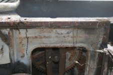
Just acquired a new (to me) E. Gould and Eberhardt shaper. This is how the name appears in the main frame casting. I have not been able to locate any serial or model numbers yet.

It was discovered by a neighbor who is cleaning out a boat shop as part of an estate liquidation. It looks like it could be a decent restoration project.

So far some of the mechanisms have moved with some coaxing, with the exception of the elevating slide and the clapper box, which seem to be stuck tight. I envision the possibility of a thorough cleaning of the ways and mechanisms and possibly repainting. Any thoughts on a historically accurate color? Under the peeling grey layer it would seem to be a dull black.

It has a 110v motor belt driving what appears to be a small 4 speed transmission that chain drives the primary jackshaft (my knowledge of nomenclature is sorely lacking so bear with me). I assume this to be a later addition to what was originally a lineshaft driven tool.

I found a reference to G & E's company history at: Ezra Gould; Gould Machine Co. - History | VintageMachinery.org

According to which, the company went by the "E. Gould & Eberhardt" name circa 1877-1883. Would it be reasonable to consider this shaper to be that old?


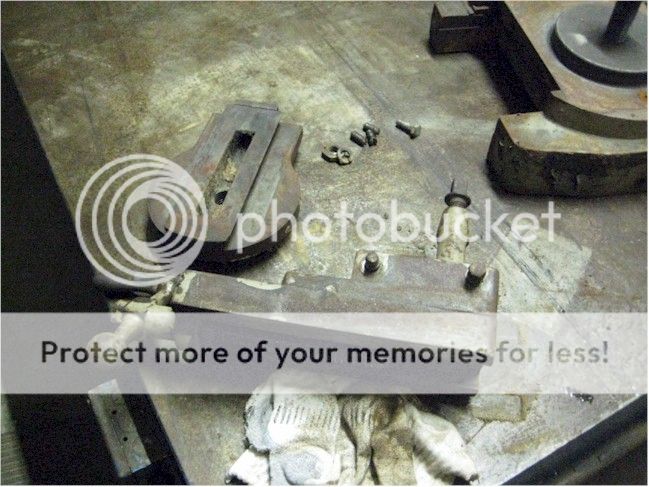
I have already begun to dismantle the swivel head and vice. I will post additional pictures of the disassembly as I can get them processed.
 
Last edited:
I am noy a G&E guy, so as to when it was built, I do not know. I will venture to say that the design features certainly scream that it was made pre-1900, so the 1873-78 is definitely plausable. No box table, exposed gearing, rather ornate column and base, makes me think 1870 period.

OK, just checked Cope's shaper book, and a machine almost exactly like yours was pictured. That particular style was covered under a patent in 1881 due to its having a stroke adjustment that worked while the machine was operating.
 
That is an earlier shaper as you suspected. It looks like the drive has been messed with. I believe it would have had a step pulley. A friend of mine has a complete one just like this and I believe he also has the original countershaft. I did not take pictures of the countershaft though. Jake

IMG_8927.jpg

IMG_8928.jpg
 
Yes, looks that old to me. You meant to say 1877-1883. And agreed, a good restoration project.

yes again, the gear driven transmission is a modern replacement for a belt drive. I would dump that, eventually. For now it is better than nothing. Unlikely, but really well worth your time to go back an see if the original parts were stashed away some place.

Edit1: Wow, two people answered while I was slowly typing. That is what happens when someone finds a great oldie, lots of enthusiasm.

Edit2: Great, a picture of the missing step pulley. You need to look for that, or eventually find a close enough to machine to fit. Cast one, or something.

Edit 3: Joe, you type as slow as me, hahaha.... Then it might be original paint under that mess. Maybe could be saved?
 
1873-1877? Yup, just about right methinks.

The transmission/speed changer appears to be a Model A Ford Tranny. You should have three forward speeds and one reverse speed.

This was commonly adapted to this use - and the nice thing is that all parts (new) are being made for this.

Although that certainly wouldn't have been used originally, of course. Instead a three or four speed cone pulley and an overhead countershaft (with tight and loose pulleys/belt shifter) would have been used.

Nice score. Black was probably the color of the day for this machine. Probably somewhere between flat black and glossy black - which might need some experimenting between the two available rustoleum sheens to achieve. Or Sherwin Williams might be able to mix up a quart or two on specification.

Keep us posted.

Joe in NH
 
Yes, looks that old to me. You meant to say 1877-1883. And agreed, a good restoration project.

Oops, thanks for pointing that out. I'll correct that. And thanks for all the replies, it seems this is truly an antique.

I'm fairly pleased with the swivel head, other than having to unstick the clapper box it seems to be sound. It well and truly will not budge so far with any of the finesse measures I've tried. I'd prefer not to have to get too aggressive.


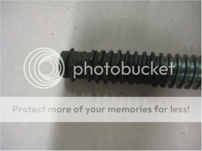
On the other hand, someone left the machine with a piece of old warped stock in the vice which allowed corrosion to form under it. I'm leaning toward doing an electrolysis bath on it to see how much is salvageable. Some of the screw is eaten away and I figure the precision surface is well compromised near the stationary jaw.


I am consistently amazed at the quality of old iron, I hardly ever encounter a frozen fastener when I'm working with it.
 
Speleoflutist: I was amazed at the pics of the vise. In my apprentice years, I ran a 36" G & E that the vise was identical to yours. This machine I am referring to was new in about 1964. G & E's are good old machines. Good luck and thanks for sharing.

JH
 
The first fruits of my labors now that all the crops are in and I have some time in the shop. I decided to tackle the vice first.

The screw being the worst part, it took some careful chipping with a spring center punch to get it out of the mobile jaw.


I let it cook in electrolysis for about 24 hours and it cleaned up enough to use. I considered making a new one, but like so many other parts of this machine, it was stamped with the number "4". So I decided to reuse anything that was obviously an original part and still reasonably serviceable. I don't anticipate working it real hard anyway, just enough to say it works.


I've begun cleaning up some other small parts with this process and it works so well I'm probably going to use it for the rest of the machine, after I can rig up a bigger tank for the main sections.

After some light scraping and masking off the machined areas I (in a fit of impatience) bead blasted the rest of the vice and repainted in a satin black. In lieu of any real idea what its original finish was it seems a reasonable color for a machine of that era.


I have yet to find anything that passes for a serial number, but the majority of parts have a 4 stamped in them. Even a few of the fasteners are stamped "4". I have the impression that this is for model assembly purposes, if that sounds reasonable.
 
Nice OLD G&E shaper.
The date sugested seems well within reason based on the design features of the machine.
Its appears to be rather complete and not badly dammaged considering the age.
The size is nice - not a beast, but not a toy.
It looks like an ideal canidate for restoration.
Even if you dont run it, it will be a great conversation piece.


The era when this was produced would have been one of steam or water power for most shops.
Flat belt drives were the state of the art and gas lights were common.
The chain drive and transmission were common add ons for line shaft machines once electrical power came along, and were added long after it left the factory.


My G&E is about 50 years younger than your machine.
The serial number on it is located on the upper right side of the main casting where the vertical way meets the horizontal way for the ram.
Yours may have one in the same location.

The main clapper box pin on a shaper is usualy tapered. If its driven in a bit deep or rust sets in, it will lock up. Caliper both ends and see if yours is tapered. If so, a well placed hammer blow or press should loosen it and allow you to drive the clapper free.


When you get her back together, think about what your going to set it on.
Machines of this era drip oil all over the place. A nice elevated base with a raised rim and sump a the back will go a long ways towards keeping the shop clean if you chose to run it.


Recognize that all the paint your removing is lead based, so sweep up well.


Recognize this machine was made before our current system of screw thread standards.
Your likely to run into 1/2 x 12, 1/4 x 24 and a variety of other sizes that are similar to what we use today but not easy to come by.
Before running a die over a thread or a tap into a hole verify the threads.
The threads are often close enough they will start properly and then make a total mess of things.
 
Last edited:
One manufacturing technique they did in a "hand built" world was to manufacture in "groups."

The wooden planemakers were famous for that. Alway in groups of 5 or 6 or 7, possibly 8.

There is something about the range of numbers from 5 to 8.

If you manage discrete information in packets less than 5, the human mind is not challenged enough to maintain a distinction. It loses concentration. In supervisor/employee relationship this can lead to boredom for the supervisor, or "oversupervision" for the employee as the supervisor tries to garner to himself more information in his responsibility.

If you manage discrete information in packets of greater than 8, the human mind tends to gloss and mix the information and it becomes difficult to maintain separation and distinction. Information overload.

Thus the US Army and other organizational groups tends to have echelon based in subdivisions of 5 to 8. Each Corporal will have 5 to 8 Privates, and each layer above this in declining echelon of 5 to 8.

So this may be number 4 of a particular group of 5 to 8?

Also, you may find a serial number somewhere. But you may not.

I also expect this one of many made using a "prototype" full size model kept in the shop as example. A craftsman would be given a task to duplicate a piece of this prototype as nearly possible as he could using only calipers or rules to make the measure. This mostly a pre-micrometer technique which only became outmoded when realization was that reading an engineering drawing and going directly to a micrometer was more consistent and most importantly QUICKER than reconstruction by repeated comparisons.

Given only calipers and and sense of 'feel' one can see why so many machine tools up until the general use of engineering drawings, micrometers and dimensionalization had not numbered dials.

Pratt & Whitney was famous for this shop methodology with variation. They would build a prototype. Then this prototype would be the example and model for all other production, which were numbered sequentially. Then, when the shop no longer had demand for this particular machine, the prototype itself would be taken and given the LAST number of it's type and sent out the door. Or possibly re-worked into a NEW prototype.

I was fortunate to own a Pratt & Whitney Planer which appeared to be Serial No. 1. It has since been established that there were likely MANY Serial No. 1s made, one for each time the planer design changed, possibly up to 5 or 6 restarts. P&W would "restart" the numbering with each design change and this planer was P&W next to last design.

Joe in NH
 
It's been a while I since I updated this thread. I've refinished most of the parts by electrolysis, opting only to blast the base; which had few machined surfaces that could not be adequately protected, and certain parts of the vice which really needed a lot of corrosion removal. Much of the reassembly is complete at this point.

The completed vice:


Assorted small parts;


I also have some reason to believe this machine may be as early as circa late 1880 to early 1881.

In the following picture labeled fig. 4 (Cope pg.71), the resemblance is almost exact with the exception of the cross rail elevator group. The text indicates this example was introduced in 1880.


The next picture shows the model patented in May of 1881. This model has the underslung cross rail elevator that my machine incorporates, but my machine is not equipped with an improved stroke adjuster. By 1884 most shapers shown in Cope's reference no longer used the underslung elevator group and had one mounted behind the apron into the rail itself.


More to come...
 
Busy days and lazy nights have caused me to neglect this thread for far too long. I owe it to those who've helped me with info and suggestions to finish this. I have finished the project some time ago and I'll try to keep the posting momentum going this time.

The problem of running electrolysis on the larger parts was solved by going to an industrial scale with an old chemical tank that I had. The sealed top allowed me to run it indoors while venting the potentially explosive gases out of the shop.


My son supervising the installation of the sacrificial anodes and the main frame of the machine.


The finished frame.


With the process of electrolysis completely striping the parts to bare metal, and since the original undercoat was some form of black, I went with a satin finish in that color. Gloss, for all its flashiness, did not seem to be something one would expect from that era. I didn't put much more thought than that into it, but it seems to look nice, if not historically authentic.

The frame after finish coat (the Monarch model A lurks undercover to the right):


The crossrail was a tad challenging to mask off with very few areas actually taking paint. Note the Rust-Oleum can... It's #7777. The finished crank arm can just be seen at the upper right.


The base, almost ready for reassembly, cures on the layout table.
 
A closer look at the crank arm, note this shaper doesn't use any shackle type linkage. The knuckle at the far end slip fits into a fork that clamps directly into the ram.


The finished swivel head. It became obvious during stripping that the clapper box had been broken at one point. It was brazed and reinforced with a screwed on side plate which can be seen just above the slide gibs. So much for ever doing any heavy work with it...


Now the final assembly starts. This picture best shows another gaff with this unit. When the babbitt bearings failed someone was not up to the task of repouring them. I can't say I blame them as that is beyond my pay grade as well. Modern sealed bearing collars were welded on and sealed bearings installed. I replaced the old bearings with newer ones, but am not going to attempt pouring and fitting babbitt.
 
The crossrail and apron installed. One modern consession I've made on this machine (and easily removable) was to include a micrometer dial in the apron feed, noticeable as the shiny metal on the right end of the crossrail leadscrew, between the advancing gear and rail casting. I felt that it would be helpful to at least be able to see where the apron feed was set at as there is originally no other provision than a good guess.


Winter of 2013's project was to build an indexing attachment for my Logan 820 and this was my chance to use it for something useful.


and finally it all comes together.


Actually the drive gears, bearings and shafts were not yet installed when I took the picture but the basic unit is otherwise complete. I didn't bother to restore the jury rigged drive motor and transmission other than to clean it up and remount it for demo work. It's old paint setting it off as non-original equipment.
 
Finishing up with a before and after. I'd like to think that if old machine tools could speak they'd say, "If we're a bit tired, it's only from building a world."


Back
Top