What's new
What's new

Pretty Precision C-Clamp....

rivett608

Diamond
Joined
Oct 25, 2002
Location
Kansas City, Mo.
I've seen micrometers that have been used as c-clamps but this is the first c-clamp I've seen that was made as well as a micrometer...... it opens to about 2"... was made by G. H. Davis maybe in the 1880s....... has screws that can tighten the main screw (kind of like some early mics) .... a knurled section to act as a speeder..... and the frame is beautifully forged, filed and polished into wonderful shape....... it feels so balanced in your hand you wish it was a micrometer....... makes you wonder just how much time did it take him to make it?
clamp1.jpg

clamp2.jpg
 
Rivett,

You did it again! Every time you post some neat tool I have to go out and find(or try to anyway)one. My latest is the Starret hacksaw you noticed in the military shop in a truck. Anyway nice C clamp.
 
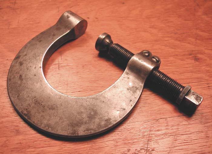
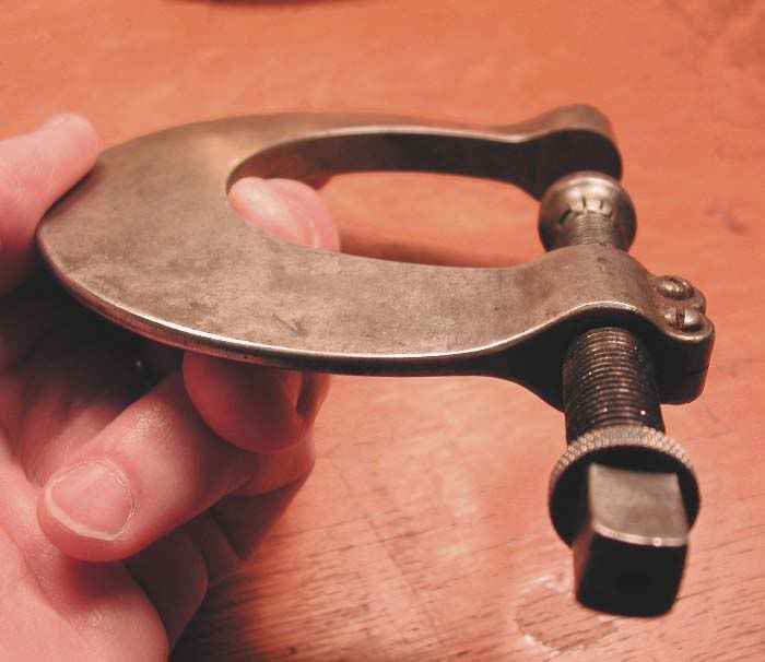
How much time to make that nice clamp?

Interesting question, not just for that clamp but for many 'old' tools, machines, clocks, jewellery etc etc

I have an idea that those guys had more hand skills than we do today, they were good with hammer and anvil, chisel and file - practised and able to make quick work of what we struggle with today.

Also, accounts I have read of large steam engine building suggest that the time taken was not the most important thing - the job had to be done right.

One story I read was about fitting some large countersunk screws in a mill engine - the screwdriver slots all had to be in line when the screws were tight!

This is probably a bad example, as most of the care that was taken was of a more practical nature - whatever it took to make a 1000-2000hp engine run night and day for maybe 50 years, and never, if possible (being the only power source) let the mill down.

Another similar aspect that fascinates me is the embellishment given to many 19th century steam engines. In particular, many municipal water or sewage pumping stations were lavishly decorated - both the buildings and the engines - they were objects of great civic pride - and yet, you can bet they were not open for the public to ever see. So why did they do it? I think maybe there was a different idea as to what was important that we can't understand today.

I am glad that as an apprentice I was allowed to learn to make things right, no matter how long it took. That is one reason why we were paid almost nothing to begin with, and then slowly were paid more over the next 4 years. Speed came later, but doing it right was the foundation (in toolmaking, anyway)

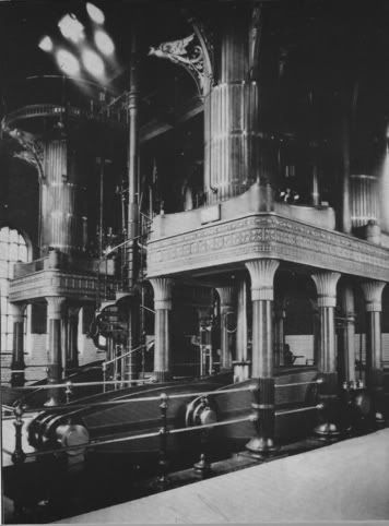
Here is a photo of one of those decorated engines, a differential compound engine by James Watt , 1885, eagles and flutes, ornate covers over bolts.

WhitacreStationJamesWatt1885differentialcompound.jpg
 
Brian It is clearly a C-clamp....... the swivel at the end of the screw would keep it from holding a setting.....

Sandiapaul...... show us some goodies your finding....
 
Cannons were very ornate for a couple of hundred years (or longer). Finally someone wised up and said "let's knock off the gingerbread, sumbitch will probably blow up anyway"
 
Peter S

You've raised some interesting points, as usual. I often see countersunk woodscrew head slots lined up, and take it as a trademark of careful workmanship, although in reality I know that it's illogical, because screws should be tightened up the right amount regardless of appearance! Having said that, I couldn't stop myself lining up screw slots when I was fitting some brass memorial plaques to park benches yesterday. I guess the screws on engines you referred to had nuts on the other side, so the objection to lining up slots wouldn't apply.

People used to do amazing things with hammers and chisels, and it would be interesting to hear from any practitioners of the art.

No doubt, Peter, you’ve read ‘The Last Years of Mill Engine Building’ by Arnold Throp, published by I.S.S.E.S. For those who haven’t, there’s some fascinating stuff in there – shrink fitting a large crank after heating it over a bonfire, a picture of a 32 foot 120 flywheel being machined (no lathe – a big pit, plummer blocks, wheel driven via the barring gear teeth), the perils of working under arc lamps with bits of white hot carbon falling off….).

Regarding unnecessary embellishment, I recall scraping thick caked grease and scale off a rolling mill stand, in a dark and dirty mill, in readiness to change the bearings, and being showered with thin flakes of glass. My scraper had struck a beautifully made ‘DAVY’ nameplate, cast in brass, with the letters filled with enamel. The sort of thing they used to put on jewelers’ shops and embassy entrances! The mill wasn’t that old, built in the early 1960s.
 
"Regarding unnecessary embellishment,"..... no such thing..... I'm only kidding..... but I thought screws were suppose to have the slots lined up...... is not why they are there? I try to if it is on something that will ever be seen. I just love to see those extra embellishments on tools and I think it is interesting how some have stayed around for hundreds of years to the point no one knows why they were done that way in the first place.... my favorite example is the finial found on most jeweler's saws.

Asquith.... for doing things with hammers and chisels see

http://www.practicalmachinist.com/ubb/ultimatebb.php?ubb=get_topic;f=11;t=000834

especially the dividers.....
 
Asquith,
The large countersunk screws I read about didn't have nuts, that is why it sounded so painful! Furthermore, I can imagine the heads had to be the same depth, so you only had one chance to get it right...

I thought I had read this in Arnold Throps book, but now I can't find it there. (One of my favourite books, I look for any books that give actual accounts of what it was like to work in engineering in past times - this is probably the best I have seen in that he gives the technical details and describes the machine tools etc).
 
Thanks for bumping this thread back to the top rivett. Beautiful workmanship on that clamp. Hard to grasp how much time was spent making it.
 
It's beautiful design and workmanship, but I doubt that it really took that long to make. I'd guess it to be a 4-hour project. A little much for C-clamp maybe, but not if you want a really nice one to keep for a lifetime.

In my musical instrument business, I make up lots of custom metal hardware in which beauty is as important as function. Hand shaping metal into pleasing curves and lines is fun! There's much more to metalworking than just cranking X and Y handles. Break free from the bonds of coordinates! :D
 
Hello Maxim;

I can't see the exact scale, but I'm assuming that the frame's about 5" across and 1/2" thick, and the screw is something like 3/8-24.

Start with a 5" square of 1/2" thick steel. Do the layout right on the top surface. Using the square sides for reference, locate & drill the holes for the screw and the two small clamping screws.

Next, bandsaw out the C shape of the frame, inside & out. Pre-drill some holes if needed to get around the inside radius. Clamp it in a vise and file out the inside of the "C" to make it smooth & fair. File the outer perimeter the same way to smooth & fair. Or if you're feeling lazy, take it over to the belt sander! While it's in the vise, use a mini hacksaw to saw the slot for the split at the two small screws. And file the small V and the rounded lumps around the small screws.

At this point, the whole frame is still 1/2" thick. Scribe guide lines on the inside and outside to show how far to bring down each side to get the triangular cross section of the right thickness. The easy way to do the rough shaping is on a "knife belt sander"; which is a vertical belt sander with a narrow slack belt. But it could also be done the old-fashioned way, with files in a vise. The final smoothing would be done with #4 Swiss files, followed by a medium finishing wheel.

The screw is turned from 1/2" bar stock, threaded and knurled. The rotating cap is also turned from 1/2" stock. The small slots for the crimp are hand sawn before the cap is parted off.

I figure about an hour to make up the screw and the cap, and about three hours to make up the frame.

It's not as hard as it looks to hand shape a part like that. It takes a good eye and some patience. And I'm not trying to diminish the quality of this clamp...the shape and lines are beautiful!

Bruce Johnson
 
................rivett,do you think this clamp has had the micrometer spindle replaced long ago with the c-clamp screw.Orherwise,why the tightening adjustment on the screw?If not the right thread pitch,could the mike threads have worn out,and re tapped into this clamp? BRUCE!!!!! NO WAY A 4 HOUR JOB! not unless the copy is a horrible hack job!!!!! Do you see how carefully that piece is made?I challenge you to try it.
 
G... no way this was a micrometer..... I have a number of other tools and the chest made by the same guy..... he did this same work on his lathe dogs..... also there is no evidence of any kind of barrel being on the end.... most micrometers have graduations on the screw that interact with those on the barrel and one of the things I mainly collect are pre 1900 micrometers, I have a number of shop made ones and have a pretty good idea of what they look like... BTW... check out these two threads for crud micrometers and micrometers from C clamps...

http://www.practicalmachinist.com/ubb/ultimatebb.php/topic/11/928.html#000000

http://www.practicalmachinist.com/ubb/ultimatebb.php/topic/11/953.html#000000

I agree with you that someone would have to be pretty good to do this in 4 hours.... I know I couldn't...... and you wonder since this was made circa 1880 how long did it take him?


Back
Top