What's new
What's new

RPC, leg voltage

gbottolfsen

Plastic
Joined
Mar 30, 2008
Location
IL.
Hi
I am new to this site, I was referred by someone on MM.com.

I have 220 volt, single phase coming into my house.
I called the power company to see about getting three phase,
they said it was not available.

The power co. told me I could get three phase by using a RPC and
that they had an old one that I could lease at no charge. What a good
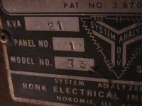
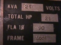
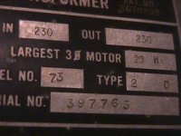
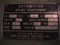
deal I thought:), until I saw what they brought, OLD, HEAVY 20 HP
rotary, capacitor start three phase motor on skids. The only reason
for no charge I could see was THIS THING IS GOING TO SUCK UP THE
ELECTRICITY:angry:

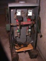
I had a commercial electriction come in and wire it, and the three
phase output to a circut breaker box in my garage.

Turned it on and started measuring voltage, expecting the voltages
I wanted=READ EVERYTHING ON THIS SITE ABOUT RPC'S.

This is what I read. [B IS THE MANUFACTERED LEG]

A TO B=248V
A TO C=240V
B TO C=294V

A TO NEUTRAL=120V NOTE: NEUTRAL IS THE ALL THE
B TO NEUTRAL=235V WHITE WIRES IN THE CIRCUIT
C TO NEUTRAL=120V BREAKER BOX, BUS.

I do not have a phase meter, or an amp meter. All the readings were
RPC running unloaded, measured at the circuit breaker box LINE IN
bus bars at the top of the box.

My question, are these voltages acceptable to run just plain 220v three phase motors from one to fifteen HP? Only one at time, though:):):)

From reading all the posts on this site I am still not sure. ELECTRICITY
AND ME ARE STRANGERS.

Thanks
Gene
 
A motor running without a mechanical load consumes little current. Likewise a RPC running without a current load uses consumes little current. It does not take a whole lot of energy to spin a shaft at 1750 RPM. It's only when you resist the rotation of the shaft on an induction motor with a mechanical load that major current begins to flow in response. Ditto for the RPC though the only loads are electrical.

The voltages you measured are actually in the ballpark and should balance further once a current load is added, i.e. when you begin to draw current to run a motor, though you should check again under load to be sure. If the voltages are still off, some tweaking with 'balance' capacitors is in order. Since the electric co is so generous, they may send a tech out to help with this, once you've determine the need then ask them.

That you got a big honkin 20 HP motor is a good thing! You can start heavy loads, even an air compressor of up to 10HP (And I mean 10 REAL HP, not big box store oil-less compressor '10 HP')

Your electric co. is very generous! I wish there were such a program here :(

Jimbo
 
Can you post some pictures of the insides? Since your manufactured leg is pretty high I am guessing that this is a "self starting" design. It only uses run caps that both start and balance, they do not drop out.

The problem is that they need more cap than you want to balance in order to start so your generated leg ends up high.

-Joe
 
RPC leg voltage [pictures]

Can you post some pictures of the insides? Since your manufactured leg is pretty high I am guessing that this is a "self starting" design. It only uses run caps that both start and balance, they do not drop out.

The problem is that they need more cap than you want to balance in order to start so your generated leg ends up high.

-Joe

Joel:
Here are the first five pictures, boy loading pictures here is a PITA!!!
Five more in the next post.
Thanks
Gene
 

Attachments

  • MVC-001F.JPG
    MVC-001F.JPG
    52 KB · Views: 155
  • MVC-002F.JPG
    MVC-002F.JPG
    75 KB · Views: 147
  • MVC-003F.JPG
    MVC-003F.JPG
    66 KB · Views: 141
  • MVC-004F.JPG
    MVC-004F.JPG
    44.7 KB · Views: 126
  • MVC-005F.JPG
    MVC-005F.JPG
    47.6 KB · Views: 122
RPC leg voltage [pictures]

Can you post some pictures of the insides? Since your manufactured leg is pretty high I am guessing that this is a "self starting" design. It only uses run caps that both start and balance, they do not drop out.

The problem is that they need more cap than you want to balance in order to start so your generated leg ends up high.

-Joe

Joel here are the last five pictures
Thanks
Gene
 

Attachments

  • MVC-006F.JPG
    MVC-006F.JPG
    44.6 KB · Views: 105
  • MVC-007F.JPG
    MVC-007F.JPG
    46.9 KB · Views: 101
  • MVC-008F.JPG
    MVC-008F.JPG
    46.5 KB · Views: 107
  • MVC-009F.JPG
    MVC-009F.JPG
    65.1 KB · Views: 109
  • MVC-010F.JPG
    MVC-010F.JPG
    40.4 KB · Views: 125
RPC leg voltage [pictures]

Can you post some pictures of the insides? Since your manufactured leg is pretty high I am guessing that this is a "self starting" design. It only uses run caps that both start and balance, they do not drop out.

The problem is that they need more cap than you want to balance in order to start so your generated leg ends up high.

-Joe

OOPS
Joel:
Had two more pictures
Thanks
Gene
 

Attachments

  • MVC-011F.JPG
    MVC-011F.JPG
    46.5 KB · Views: 147
  • MVC-012F.JPG
    MVC-012F.JPG
    67 KB · Views: 159
Can you post some pictures of the insides? Since your manufactured leg is pretty high I am guessing that this is a "self starting" design. It only uses run caps that both start and balance, they do not drop out.

The problem is that they need more cap than you want to balance in order to start so your generated leg ends up high.

-Joe

Looks like you're right, Joe as I don't see a contactor anywhere in the pics, just lots of caps. I guess from the electrical co's perspective a contactor is something that can break.

Jimbo
 
RPC leg voltage

Looks like you're right, Joe as I don't see a contactor anywhere in the pics, just lots of caps. I guess from the electrical co's perspective a contactor is something that can break.

Jimbo

Hi Guys
Just some more info, lights really go dim upon start, and my electric meter really starts rotating a lot faster, with no load on the RPC. Can't measure how much faster!

Also a question on wiring-Three phase=three wires to hook to my load motor. Load motor has four wires, red, black, white and green/some are bare copper. where does the fourth wire go?

I appreciate all the help.
Gene
 
The RPC looks like a self starting one. You could try removing some of the caps and see if it still starts, in order to lower the voltage in your generted leg, but if your machines aren't complaining I moight be inclined to leave it alone.

The fourth wire is a safety groung. It goes to ground (green or bare) not neutral (white).

-Joe
 
"The RPC looks like a self starting one."

Most of those older RPCs are self-starting.

That this one is self-starting can be seen by the large number of run caps, and no starting contactor or starting means.
 
RPC leg voltage

The RPC looks like a self starting one. You could try removing some of the caps and see if it still starts, in order to lower the voltage in your generted leg, but if your machines aren't complaining I moight be inclined to leave it alone.

The fourth wire is a safety groung. It goes to ground (green or bare) not neutral (white).

-Joe

Joel
I found the chart below on Wikapedia before you posted, now I am
more confused [DOES NOT TAKE MUCH] than before I posted.

Should I get a five cord to connect my machines?
Line 1=Black
Line 2=Red
Line 3=Blue [my chords or RPC I have no blue??}
white=White, Neutral [all white wire in CB box?
Green=Circuit breaker box case?

Is the above what the chart [attached] is trying to say?

JOE I CAN NOT ATTACH THE CHART IT KEEPS SAYING TOO BIG, TOO BIG, TOO BIG. IT IS ONLY A WORD DOC.

Basicaly the chart says
L1 is black
L2 is red
L3 is Blue
Neutral? is white/gray
Ground/protective earth is green/green yellow strip or bare copper
wire.


Sorry to be so picky [ignorate]
Gene
 
Only 120/208 Y and 277/480 Y "utilization equipment" requires W, and hence five wires.

208, 240, 480 and 600 three-phase does not use a neutral, hence these only require four wires: X, Y, Z and G.

These assume a ∆ source, but it doesn't matter if the source is ∆ or Y as there is no neutral conductor to supply the "zero-sequence" current.

208 and 240 should use SJ ("300 volt class") or S cordage; 480 and 600 must use S cordage ("600 volt class").
 
translation please

Only 120/208 Y and 277/480 Y "utilization equipment" requires W, and hence five wires.

208, 240, 480 and 600 three-phase does not use a neutral, hence these only require four wires: X, Y, Z and G.

These assume a ∆ source, but it doesn't matter if the source is ∆ or Y as there is no neutral conductor to supply the "zero-sequence" current.

208 and 240 should use SJ ("300 volt class") or S cordage; 480 and 600 must use S cordage ("600 volt class").

Sir
"XYZG"??????????????
Please translate where did zyzg come from?
I am talking L1, L2 etc [SEE MY POST!!!]

I don't care about wye, delta ????????
The way I understand it hooking what to what, it will run either way.

Please read my last post and give me a clue.

Thanks
Gene
 
You should only need 4 wires.
Three hots and the protective earth / safety ground.

Most 3 phase machinery does not require a neutral (white) so you should not need to run one.

The hots can be black, red, blue, orange, brown or yellow. Usually the two utility hots are either black or red and the generated hot is blue or orange.

The PE / safety ground is green or bare.

-Joe
 
Gene I'm going to ask one question I have not seen yet in this thread and I'm
sorry if it has been answered already:

What equipment are you going to run with the converter? Specifically, how many
horsepower will it be required to run?

Thank you - Jim
 
RPC leg voltage

You should only need 4 wires.
Three hots and the protective earth / safety ground.

Most 3 phase machinery does not require a neutral (white) so you should not need to run one.

The hots can be black, red, blue, orange, brown or yellow. Usually the two utility hots are either black or red and the generated hot is blue or orange.

The PE / safety ground is green or bare.

-Joe

Joe: [SORRY BEEN CALLING YOU "JOEL" My bad sorry!!!

Thank you, thank you, THAT IS WHAT I WANTED TO KNOW, espicially
the fourth wire, motor frame to CB box [case] ground. really appreciate that.
Thanks
Gene


NEXT QUOTE


SORRY JIM, DID NOT KNOW HOW TO QUOTE YOU, WITH OUT COPYING

"Diamond
Join Date: Feb 2004
Location: peekskill, NY
Posts: 9,788
reputation_balance.gif


icon1.gif

Gene I'm going to ask one question I have not seen yet in this thread and I'm
sorry if it has been answered already:

What equipment are you going to run with the converter? Specifically, how many
horsepower will it be required to run?

Thank you - Jim"


Jim
I have up to 7 three phase motors from one HP to fifteen HP, the 15
HP being an air compressor, but only one at a time. Possiably a 1 HP[drill press, mill, belt sander, etc.]
and the aircompressor could run at the same time, that will be the most, Jim

Thanks
Gene
 
With this type of RPC, the smallest load the can run off of this converter at one time is 25%, so if you have a 20Hp RPC the smallest motor that you can run by itself is a 5hp
 
RPC leg voltage

With this type of RPC, the smallest load the can run off of this converter at one time is 25%, so if you have a 20Hp RPC the smallest motor that you can run by itself is a 5hp

Sir
So if I need to run only a one HP motor, what do I do?

Why, what goes wrong if, I run one HP motor only?

I need all the idea's I can get.

Thanks
Gene
 
If you plan on running a 1Hp motor off of this type of converter, you will burn out the winding on the 1 hp motor. The reason is that there will not be enough load on the selfstarting RPC to drop down the high manufactured voltage leg.
To solve this problem, you would have to remove some of the run capacitors after the RPC was started and up to speed.


Back
Top