Howard,
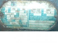
The full load amps seem extremely high. A NEMA design C, 10 hp motor would have a full load amp rating of approximately 27 amps. I think a photo of the motor nameplate is the next item needed to help figure this out. Thermo King is a manufacturer of refrigration units primarily for refrigerated trucks and such. I do not know what kind of motors they make or re-label. Please recheck the FLA rating and make sure you are not looking at the locked rotor amp rating (85 would likely be too low for the locked rotor rating)
We still need the number of leads and the wire numbers. Since it is dual voltage, we suspect it will have nine leads
You can get run capacitors from
www.surpluscenter.com. I am ordering from them presently for two 7-1/2 hp RPCs I am building. They ship quickly and their prices are very reasonable. I seem to remember about $7 for a 40 microfarad (mfd) size oil filled motor run capacitor, but I have not been on line this week to check.
For a starting circuit you need a potential relay (Steveco 90-66 which is about $22 from
www.patriotsupply.com, a 3 pole, 240 volt coil, 40 or 50 amp rated contactor which is about $20 or less on ebay, and two electrolytic capacitors, 250 volt rated, and 276-324 micro farad rated, these are about $10 each and make sure they are new). None of these items are in the lights you are talking about. The lights do contain oil filled run capacitors of about 28 mfd rating. I used to have lots fo these but used most of them. Do not buy any of the components till you have the motor wiring figured out and know that it will run.
The starting circuit components will cost about $60 and you still need a way to turn the power on such as a 60 amp disconnect or a 60 amp, 240 volt coil, 3 pole contactor and a stop and start push button set. More on all this stuff after you have the motor working.
The above comments are just to give you some idea of what is needed to make the RPC self starting. I did not include prices and quantities for the run capacitors since you may not need them.
Bruce Norton
Kingsport, Tn