What's new
What's new

Variable Speed DC Drive for Oliver motor

pgopinath

Plastic
Joined
Apr 28, 2008
Location
Minneapolis
First post and an absolute beginner in restoring machines.

I will be picking up an older Oliver 25 patternmaker lathe. The headstock spindle is directly driven by a 2HP 230VDC/8AMP motor.
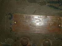
MotorLabelComp.JPG

The motor is supplied from a outboard transformer/rectifier that converts 115VAC to 230VDC. This rectifier unit is a huge 200lb unit that is about 18"x30"x18".

RectComp.JPG

The speed control is through a circular (copper wound?) rheostat that goes 400rpm to 2000rpm.

RheoComp.JPG
RheoComp2.JPG

I am hoping to replace the existing drive electrics (rectifier, rheostat) with a solid state DC drive that would give me speed control from close to zero rpm to 2000 rpm. Ideally, the solid state drive would take 115VAC/230VAC and output the variable DC to the motor.

Even more ideally, I would like to find a step-pulley headstock for this and convert it to a 3phase VFD driven motor but I don't think I will be that lucky. But if someone has any pointers I will take them.

Can someone give me some guidance on sources for the DC drive I am looking for or for alternate ways of doing what I am trying to do?

Thanks in advance
Prabha
 
One of the most economical ways is an SCR control such as made by KB and relabeled by Baldor and others, both sites will give you the necessary model to pick from, i.e. 120/240, HP etc, some models cover both voltages, you didn't mention if the motor has a wound field, but they also have a field supply.
If you already have a good motor, this may be the best option over a VFD & 3 phase motor.
Depending on what type of control you need, they come in 2 quadrant or 4 quadrant,
The two quad. allows speed control in one direction, the armature has to be swapped over to change direction, the four quadrant gives reversing and braking.
All models offer Tach feedback if you want really precise speed control.
Ebay is a source, or your local Baldor dealer.
M.
 
DO NOT get rid of the original motor.

The problem I see is that most speed controls are 90/180v DC. You can't get the full speed out of the motor using those. I'd use a variac with a bridge rectifier, and a capacitor.

A couple questions, first, does the motor have a separate field? If it does there should either be a separate terminal all by itself on the side somewhere, and it should get a separate DC voltage output. It may or may not share a ground with the armature (where the brushes connect). If it's got big permanent magnets inside, it doesn't have a field.

WHY do you want to get rid of the original speed control setup, and does it work??? If the original speed control works, I wouldn't screw with it. I doubt you'd get very good control below 400 rpm anyways.

Here's a couple cheap variacs for you, just pull the motor off.

http://www.fairradio.com/catalog.php?mode=viewitem&item=3033

http://www.fairradio.com/catalog.php?mode=viewitem&item=3036
 
DC Motor

pgopinath,

I have to agree with Junkyard--Don't get rid of the original motor setup if it works ok. That transformer unit can easily be replaced by a standard used dry transformer wired as an autotransformer to step up voltage and a $5 full bridge rectifier (1"x1"x3/4") to convert to DC. If necessary the rheostat can be replaced with a Variac to vary motor speed (the variac must control the AC before rectification). The motor is shunt wound and is not a permanent magnet motor. It has a wound armature. From the nameplate it appears that the field and armature are both 230v since a separate field voltage is not specified.

I use several DC motors in my shop all 115 AC converted to variable voltage DC using full bridge rectifiers and Variacs. They include Perm magnet, shunt and compound wound DC motors.

A variac will allow control below 400rpm, but it's a wood lathe so the lower rpm's are not that useful.

Whatever you do don't get rid of that motor assuming it's still working.


Good Luck,

Joe
 
It appears that the unit has a variac already to control it, ironically, if the present P.S. does not have capacitors, I suspect not.
Then when using full speed it will be identical to using one of the suggested SCR controllers as they are in fact a bridge connected across the line, when fully turned on (Max rpm) the SCR bridge is no different from a fixed bridge.
In the 2 quadrant version only two of the rectifiers are SCR's, the other two are normal rectifiers.
BTW, if you DID want to increase the rpm, you could rig up a simple field weakening circuit above a certain RPM.
M.
 
Last edited:


Back
Top