peterh5322
Diamond
- Joined
- Dec 15, 2002
- Location
- Monterey Bay, California
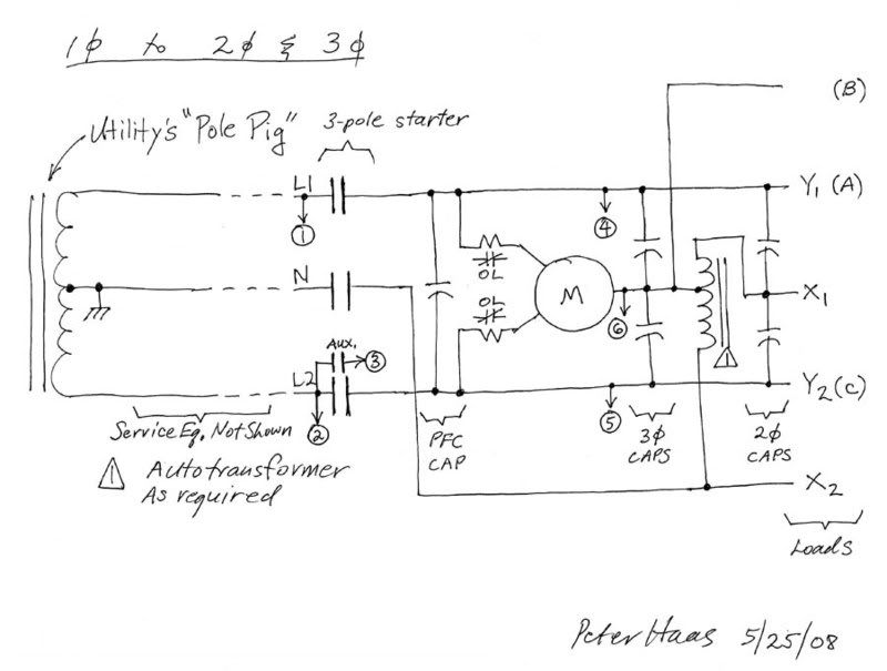
Back by popular demand is an old post (since lost in the conversion to the new software) for a method of converting single-phase to two-phase AND three-phase using a single idler in an RPC system.
This method simulates a Scott-T, as do most RPCs of the balanced type, but in addition to, or instead of three-phase, this method produces two-phase, as is required by machinery which was formerly installed in Buffalo/Niagara Falls, NY/Niagara Falls, Ont and Philadelphia/Camden/Reading.
Three-phase is taken off as usual, from L1/A, B and L2/C.
Two-phase is taken off in a new and inventive way, from L1/Y1 and L2/Y2 and X1 and N/X2.
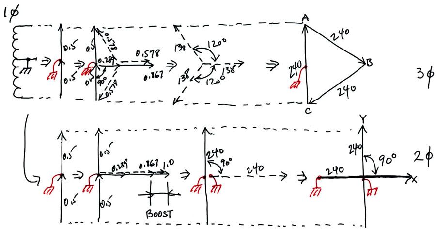
An autotransformer is used to get the 0.867 to 1.0 "boost" in the X1-X2 phase.
This is one of the very few cases where N is required in an RPC system.
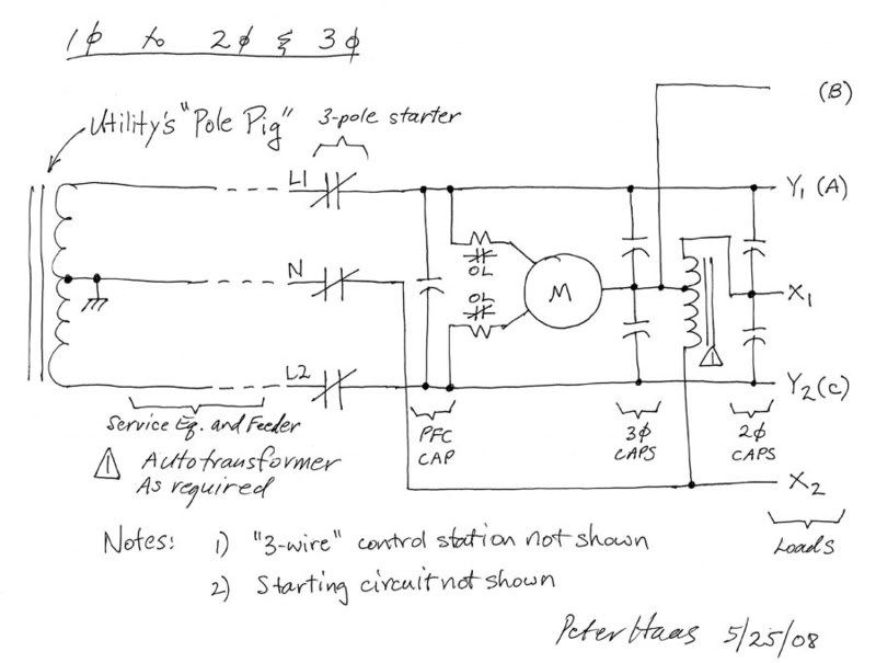
This method simulates a Scott-T, as do most RPCs of the balanced type, but in addition to, or instead of three-phase, this method produces two-phase, as is required by machinery which was formerly installed in Buffalo/Niagara Falls, NY/Niagara Falls, Ont and Philadelphia/Camden/Reading.
Three-phase is taken off as usual, from L1/A, B and L2/C.
Two-phase is taken off in a new and inventive way, from L1/Y1 and L2/Y2 and X1 and N/X2.
An autotransformer is used to get the 0.867 to 1.0 "boost" in the X1-X2 phase.
This is one of the very few cases where N is required in an RPC system.
")