What's new
What's new

potential relay rpc question

rsal

Aluminum
Joined
Mar 8, 2005
Location
Danville IN
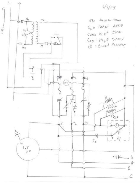
I have been reading the board and have answered most of my questions on a rpc. I have a Hardinge DV-59 with a 3/4\3/8 hp dual speed motor that I want to run with a rpc. I am looking at using a potential relay (steveco 90-66) and a 1 1/2 hp motor that a friend gave me. I do have some questions that I need answered.

How do you calculate the resistor value to use as a bleed resistor?

If I understand using a motor starter (Square D 8536) you are to size the heaters for the load only. Is this correct even on the rpc?

I have drawn a diagram for wiring the electrical box and would like to make sure I have it right before I do the wiring. If it needs touching up, let me know what and why as I am learning as I go with machinery. I do understand the basics of electricity but do not deal with it daily (like I do drainage systems) so I want to be certain it is correct before I go forward. I do have a friend that works with electricity daily but we work different shifts and do not get together enough for me to pick his brain on this.

Anyway, if everyone could look at this and comment, I would be greatful.

rsal

phaseconvertorelectrical.jpg
 
Your diagram really looks pretty good. I run my hardinge machines like that with a 5hp
idler, but I don't do any tuning at all on it, no capacitors. If you tune yours like that,
you basically read the instructions from Fitch Williams to get the values correct. After
you have the two capacitors sized correctly, you might consider going back and adding
in power factor correction in the form of a capacitor from line to line. This is tuned to
basically minimize reactive current flow, you mimimize the incoming amp clamp meter
reading. But as fitch would say, do that after the tuning is done.

I'm not quite sure what the symbol "M" in the circle is, in the control circuits. But
it's pretty clear you have a control circuit powered by the transformer. You probably
should fuse the secondary of the circuit for the wiring size used (which will be a lot
less than the load wiring, right?) AND you need to bond the secondary of the control
transformer to ground. It's a separately derived service so one side needs to go
to green wire ground, or to chassis.

It's not real obvious to me but there must be some kind of disconnect upstream of
your incoming lines on the diagram, otherwise the control transformer would be live
all the time, and you probably don't want that.

The bleed resistors are in parallel with the motor windings, with no contacts interposed
between the capacitors and the windings. So the bleeders are not strictly needed but
the idea is you want to bleed the charge off the capacitors in 10 seconds or so, so you
figure the RC time constant and go from there. Just be sure to figure the power rating
of the resistors. It's not a bad idea to put the bleeders on in case something goes open
and you are in there trouble shooting. My rule is you never rely on those anyhow.
I always screwdriver across any nastly looking oil capacitors. Sometimes you get a suprise.

Jim

Otherwise
 
Thanks Jim

I copied the motor starter diagram from Square D's website. I think it is the coil for the contacts (motor starter has a 120 coil which is why I am adding the transformer)

I have the basic electric knowledge from building maintenance work I used to do but deal daily with water drainage so I never have much of a chance to do much electric work except for changing sockets and switches when they can not find anyone else.

Most of the symbols a got from the square D or similar web sites.

Again thank you

rsal
 
"How do you calculate the resistor value to use as a bleed resistor?"

15 K, 5 W should be fine.

Usually, I place such a resistor across each capacitor, so, should I reconfigure the RPC, as during tuning, a bleeder will always be present.


"If I understand using a motor starter ... you are to size the heaters for the load only. Is this correct even on the rpc?"

For the magnetic motor starter of an RPC, you size the heaters for the FLA of the idler.

Recall that the A and C phases are passed-through.

You protect the idler as to its FLA, and this is, essentially, the maximum current provided by the "manufactured" phase.


Back
Top