What's new
What's new

Need some direction with RPC build.

jminer99er

Plastic
Joined
Jan 14, 2008
Location
Sacramento
Heck, where do I start?!

Hello people, I have been in the background reading all this great info for about four months, while gathering electrical stuff for a RPC. I am an electrician, but I have no experience with motors or industrial control work. (Starters, relays, contactors) I did take electronics and have a general understanding.

My dad is a machinist. (Likes to build small steam engines and such) He had a static phase converter that smoked about four years ago, and is too frugal to buy new.

He has two, 3ph mills, and a grinder. The grinder is 2hp. His Kempsmith mill is 3hp. His Bridgeport has three motors on it the biggest is 1/2hp.

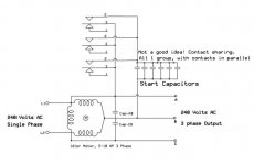
I just picked up a Baldor EM3313T Super-E 3ph 10hpDP motor, I have a bunch of run caps, and about 800mf for start caps. I have two 60a 3pole disconnects. I have a bunch of Square D magnetic starters, Nema0 (which I think is to small) Nema1 (which gives a 7.5hp at 230v and 10hp at 460) I don’t have any Nema2 . I also have a few Nema3 (which I think are to big)

I do have a three phase distribution panel I’m going to use.

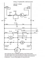
I’m trying to build according to Fitch’s design for now to get my dad started. (Bells and whistles later)

I have a few questions… (a bunch)


What size contactors do I need for the run contactor? What size for the start contactor? Do I only need two contactors? I have two Arrow Hart contactor that says "1ph 240v 5hp, and 3ph 240v 10hp" its rated for 40A. I have a GE that says "40A 240-600V 1 or 3ph" will one of those work? Will 40A suffice for my contactors? I also could rob a contactor off the Nema1 Mag starters if I need to.

Will I need a Steveco pot relay too? Oh, I have a few Potter & Brumfield time delay relays, I’m not sure where they would fit in circuit.


I do have a few control transformers that would work pri240v sec120v, but the contactors I have are 240v coils, all except one 120v contactor on a Nema1 starter. So for controls I can’t go off of Fitch’s and Im not sure how to do it.

What AWG should I pull to the idler motor? (10hp with 28 FLA) The distance would be about 50’. The wire size would tell me what size breaker to feed the idler with. Let’s say I pull #6 wire, two hots and a ground for the idler, should I bring a neutral too, and do I have to pull an additional dedicated 240v circuit for controls?

How do I protect each machine? (Where to place fusible disconnects?)

Example: from the 60a breaker in my panel run #6 wire to a 3pole fusible disconnect, then to my idler. From the idler take #10AWG to the three phase distribution panel. Bring all the machines to the three phase panel. Being that I only have 15a breakers for the three phase panel, I will have to wire in some fuses for each leg. (I think) The breakers I have are way to expensive to buy they are type EHB, or I would look into getting smaller ones.

This has been my obsession for months now and im ready to build!


Thank for taking your time and reading this, and thank you in advance for any input!
James
 
I just picked up a Baldor EM3313T Super-E 3ph 10hpDP motor

Hey you're a "miner" too. Don't know why but I think I remember reading somewhere that super-E motors are not the best for RPC's. But if it is cheap or all that is available, then why not.

I have a bunch of Square D magnetic starters, Nema0 (which I think is to small) Nema1 (which gives a 7.5hp at 230v and 10hp at 460) I don’t have any Nema2 . I also have a few Nema3 (which I think are to big)

What size contactors do I need for the run contactor? What size for the start contactor?

I used two size 2 contacters. If you only have one bigger one use it for the start contactor.

I do have a few control transformers that would work pri240v sec120v, but the contactors I have are 240v coils, all except one 120v contactor on a Nema1 starter. So for controls I can’t go off of Fitch’s and Im not sure how to do it.

If I recall right, FW design did use a control transformer and low voltage coils, but I don't see why you cant use the same design, just without the transformer. I happened to have a lot of low voltage coils so I used them, by pulling a neutral into the box.

What AWG should I pull to the idler motor? (10hp with 28 FLA) The distance would be about 50’. The wire size would tell me what size breaker to feed the idler with. Let’s say I pull #6 wire, two hots and a ground for the idler, should I bring a neutral too, and do I have to pull an additional dedicated 240v circuit for controls?

I think you mean to say 3 hots and a ground to the idler. The single phase line will go to your box. That should be sized at 6 AWG (FW uses size 8). I would then use size 8 to the motor and 3 phase panel. I suppose you could use 10. As for the neutral: only if you want it for low voltage controls. As for the dedicated 240 V circuit: no.

Lots of more knowledgable people here than me though. Good luck.

Craig
 
James,
Just to clarify, are you planning to run two, #6 (240 V single phase run) and ground, to a three phase panel, that will also house the fuses/breakers, contractors, run and start capacitors, and output lines (A, B, & C) to your three phase distribution to the machines, and then run three, # 8's (or #10's) and Ground, from the panel, out to the idler motor 50 feet away? Joe
 
Craig,

Yes, I do dredge gold. lol I just re-read what you said and missed the "too", then looked at your name! :)

So, I should use the contactor off the Nema3 magnetic starter?? Its good for like 20hp at 230v (I think) I was also wondering if I could just derrate everything and basically size everything for a 7.5hp motor, and use the Nema1. (not sure though)


I think you mean to say 3 hots and a ground to the idler. The single phase line will go to your box. That should be sized at 6 AWG (FW uses size 8). I would then use size 8 to the motor and 3 phase panel. I suppose you could use 10. As for the neutral: only if you want it for low voltage controls. As for the dedicated 240 V circuit: no.

Hmm how do I word this. I mean the input would only be 240vto the idler. Like A & B Once the motor is running, and generating the artifical phase, I would then run the output A, B, and C into the three phase panel.

As for the dedicated 240 V circuit: no.

So I can scab off A and B suppling the idler for 240v controls?

A neaural would be a good idea for 120v pilot lights.

Joe

I did the above statement clarified any info?

The thought did cross my mind to have everything inside the 3ph panel. I think there is enough room for controls. At first, I was thinking of a seperate enclosure.
 
"I mean the input would only be 240vto the idler. Like A & B Once the motor is running, and generating the artifical phase, I would then run the output A, B, and C into the three phase panel."

If you were using a three-phase magnetic motor starter, you would normally forward-feed the three-phase A and C phases (corresponding to single-phase L1 and L2) and then back-feed the three-phase B phase (corresponding to the manufactured phase).

All caps, and the starting circuit, would be on the load side of the starter.

Any size idler could be accommodated by an auxiliary contactor which would have multiple poles, rated 50 amps, with a maximum of 550 µF per pole. A three-pole contactor could accommodate 1650 µF starting capacitance.

A Steveco 90-66 potential relay would activate the auxiliary contactor.
 
To simplify your problem you will need to make a few decisions.

Fitch William's design does not use a potential relay. He uses a switch you hold in until the idler is started. With this design you can use run caps or not use them based on what you want the RPC to do. It is best with the run caps.
Fitch used a low voltage control which requires a control transformer. If you use 240 volt coils in the contactors then you do not need the transformer.

Some of the designs posted here do use potential relays. The potential relay will break the starting circuit once the idler is up to speed. If you build without run capacitors you should not use the Steveco 90-66 potential relay as your generated phase voltage may be too low to trip the Steveco. I do use the Steveco and I do install run caps as I build the RPC.

You need to decide on:
Starting method
Control voltage
Run capacitors or no run capacitors.

Once you answer these questions you will know what type RPC to build. Since you do not understand motor controls I will suggest you pick a design and stick to it. do not try to mix and match unless you understand what you are doing.

I tried to post a connection diagram for one of my RPCs but the file is 320 Kbytes and can not be attached here. Here is a simplified diagram which shows how it works but does not show where to make all the connections. This is a 7-1/2 hp diagram and is the only one I have on the computer at the moment. The circuit is the right size for a 10 hp and so are the componets. You would need more capacitance though.
 

Attachments

  • 7.5 hp RPC.jpg
    7.5 hp RPC.jpg
    65.3 KB · Views: 9,835
James,
Just to add to what Peter mentioned.
The RPC manufactures one leg, "B" and two phases (AB, and CB). The manufactured leg should be labeled, B phase, and the recommended wiring color for B, should be Orange. I chose Red for A and C since they will be easy to identify when you change rotation, simply switch the two reds [at the machines] for correct rotation. For best results, the manufactured leg should not be connected to control circuits or switched in reversing circuits. Switch A and C instead. Joe

Edit: The 135mf start capacitor shown is for my 2 HP idler motor. For a 10HP idler, you will need a lot more!
 

Attachments

  • 1Ph_3PhMotor.jpg
    1Ph_3PhMotor.jpg
    63 KB · Views: 10,741
Ahh the all knowing Peter. Honestly, I have been reading post for months and everytime you reply with key info, im always scratching my head! lol

Peter, what is meant by;

and then back-feed the three-phase B phase

and

Any size idler could be accommodated by an auxiliary contactor which would have multiple poles, rated 50 amps, with a maximum of 550 µF per pole. A three-pole contactor could accommodate 1650 µF starting capacitance

So 50a three pole would be good for a power contactor up to 1650uf of start capcacitance? I think they are 40a FL and 50a Resistive (what ever that means)


If i was using a three phase motor starter, should I? e.g like the Nema3 before the idler? So from my garage panel run wire to a mag starter. (going off memory) (In L1 and L2 then T1 and T2 to A and C?) Im still wondering if I should just use the coils/contactor off the mag starter for a power contactor? Nema3, and not Nema1, and im guess the 40a contactors I listed wont work, or arent right?


Toolnut, I will send you a PM, I would like to peek at the schematic thats to big. Thx

Toughtool, gothcha! So if I need 240v I can take it before the idler off of A and C? No need for dedicated 240v control circuit.

Once again guys, THANKS for being so patient and understanding.

I will try to upload some pics...

http://img102.imageshack.us/img102/341/img0678mp2.jpg

http://img102.imageshack.us/img102/3521/img0684jc9.jpg

http://img49.imageshack.us/img49/2480/img0693ff0.jpg
 
James,
Love your shop!
Yes, use the 240 volt coil contactors if you have them. Saves using a transformer and the L1, L2/A, C lines are where you would connect it, with suitable fusing of course. Actually you should be able to take it anywhere before a relay opens the circuit. I used a two pole relay to connect the single phase L1 & L2 lines to my RPC circuits and used a pick and hold relay to hold this closed. Opening the holding circuit (a N/C, Stop switch) or a power loss, will drop the RPC and not allow it to restart automagicly, when power is restored. A safety feature since I use a pushbutton to start my RPC instead of a Stecevo 90-96 potential relay. So I had to connect my control transformer at this relay. Otherwise I would not have had any voltage to pick the relay.
I would use the largest contractor you have for the starting capacitors, and if it has multiple contacts, wire the capacitors in groups, then connect a group to each contact. i.e. Set of three contacts, three groups of capacitors. See attached schematics. Do not wire the contacts in parallel on the capacitor side. If wired in parallel, contact sets with lowest resistance would get all or most of the load. Dirty contacts would get the lightest or no load.

Somewhere Peter listed the current requirements for contacts needed for large motor starting capacities, and how to compute them. A search may find the thread.

I wrote a post in Dec 07, about using current transformers for accurately measuring your currents, using a 0-2 volt digital meter. Don't know if you read it or not. The thread is 146431 if the following link does not work. Joe

http://www.practicalmachinist.com/vb/showthread.php?t=146431
 

Attachments

  • RPCRunCap1.jpg
    RPCRunCap1.jpg
    23.4 KB · Views: 688
  • RPCRunCap2.jpg
    RPCRunCap2.jpg
    22.1 KB · Views: 365
Your shop...

Hey Jim-

If you put about twice as much more stuff in your shop, Flooded it with mud, and then drove an F4 tornado through the middle...

...It'd look exactly like my brain! :-D

I'd be willing to bet that you don't have a key-duplicating machine in there...
(but I sure-as-heck won't bet MUCH!)
 
By back-feeding the B-phase through the three-pole contactor which also controls the A/L1 and B/L2 lines, whenever the contactor interrupts the single-phase source, it also interrupts the manufactured phase, thereby removing all power to the load motors.

I suppose back-feeding is an imprecise term. However, it is the correct term if one is using a panelboard with a multiple-pole breaker, and two poles are outputs (to A and C), whereas on pole is an input (from B).

In this specific case, a "back-feed" kit is required to semi-permanently hold the breaker in the panelboard.
 
Toughtool, thanks, its my dads shop. (and thats just the view to one corner)

I did a few searches on
Somewhere Peter listed the current requirements for contacts needed for large motor starting capacities, and how to compute them
but didnt find the thread. :(

Dave,
If you put about twice as much more stuff in your shop, Flooded it with mud, and then drove an F4 tornado through the middle...

...It'd look exactly like my brain! :-D
Good description! (no key-duplicating machine, so you would of won that bet)

Peter, I understand what you mean by backfeeding, thank you!
 
Peter,
Could you help me understand why this is necessary. Would the manufactured phase not be dissconnected when the power was cut to L1/L2, except for maybe a split second?
Thanks, Dustin
By back-feeding the B-phase through the three-pole contactor which also controls the A/L1 and B/L2 lines, whenever the contactor interrupts the single-phase source, it also interrupts the manufactured phase, thereby removing all power to the load motors.

I suppose back-feeding is an imprecise term. However, it is the correct term if one is using a panelboard with a multiple-pole breaker, and two poles are outputs (to A and C), whereas on pole is an input (from B).

In this specific case, a "back-feed" kit is required to semi-permanently hold the breaker in the panelboard.
 
The diagram below shows back feeding the manufactured phase (labeled T-3) . The fused disconnect or mag contactor then provides overcurrent protection for the manufactured phase.

-----------------
Barry Milton
 

Attachments

  • rpc1.jpg
    rpc1.jpg
    27.7 KB · Views: 1,992
The diagram below shows back feeding the manufactured phase (labeled T-3) . The fused disconnect or mag contactor then provides overcurrent protection for the manufactured phase.

-----------------
Barry Milton

Barry,
I understand what is going on here, what I do not understand is why. The other two legs are not hooked up in this manner.
Dusitn
 
The other two legs are not hooked up in this manner.

If the other 2 legs from the RPC were to be connected to the line side of the disconnect, the RPC would power up as soon as the single phase breaker was turned on.
The question that I have is, lets say the RPC was running a piece of equipment rated at 10hp. That would give us a amp rating about 26amps at 230vac. So the current draw thru the L2 fuse would be 26amps, but the current draw at L1 and L3 fuse would be 45amps. Can you by code have different size fuses in the same disconnect switch?
 
Not to dig up zombie threads but I seen somewhat of a schematic diagram up above for a 7.5HP RPC . I was just wondering if anyone on here had a true schematic for a 7.5, 10 or even 15 HP RPC with parts list and some details on construction on hand that I may obtain. I would REALLY appreciate it. If not maybe point me in the direction to where I can find one. I have started a thread of my own but thought maybe some of the posters in this thread may see the thread revived and contribute agian to the cause.
Thanks again,
Tester
 
Hey man thanks a lot for that bit there. Better than anything I have found yet. I have now only one concern after reading your post and some further reading. I talked to the guys out at elimia converters and phoenix and they seem to wanna sell me a 7.5 HP converter but the further I read I seem to conclude I will need a 10HP converter. I have a 60" between center metal lathe 5HP motor gear head no clutch. Between jogging and frequent on off with large parts or if in high gear it may put a strain and not start. I don't know what are your oppinions on this? I think I could come across a larger idler motor no prob just sizing all caponents will be a prob for me as I would be worthless at designing one of these units. SO I am at the mercy of others and need for detailed schematics.

I can follow are your parts list and schematic diargram Now that assuming on this 7.5HP rpc. Do you think this would be suffecient?


Back
Top