What's new
What's new

Changing a grinder from 440 to 220?

Forrest Silas

Aluminum
Joined
Mar 31, 2005
Location
Clanton Alabama
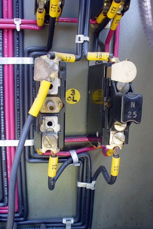
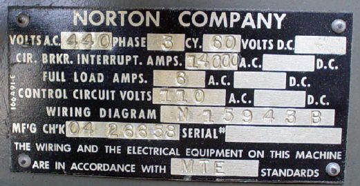
I recently bought a Norton surface grinder that is set up for 440 3 phase. I don't have a transformer. I did notice that the spindle motor and hydraulic pump motor are 9 wires and have diagrams for wiring to 208-220 / 440. The tag in the electrics box says 440 3 phase. Here is a picture of it.


Cnv0096.jpg


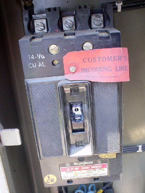
Also, the switch on the main disconnect inside the box is broken.

Cnv0094.jpg


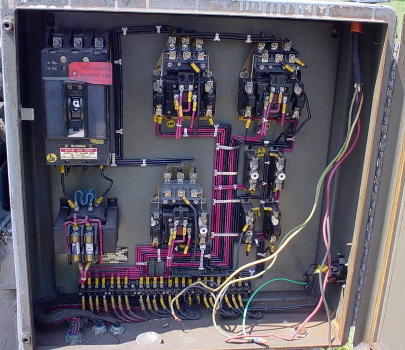
Here is an overall view of the box

Cnv0093.jpg


I plan to run this machine with a RPC. What would it harm to bypass this box, wire the motors for 220, and use toggle switches to turn the motors on and off?

Thanks,
Forrest
 
Hi John, I thought about sending you a PM about how to get this thing going, but I figured I had pestered you too much already.:o

I forgot to mention that I would put it on a 10 amp breaker, which I figured would protect the motor. I suppose I could add fuses too.

If this is not a good plan, would it be feasible to change the existing setup to operate on 220? In addition to the broken switch shown, the table feed switch and stop switch on the front of the machine are broken.

Thanks,
Forrest
 
You should be able to rewire the motor to 220V and change the input on the control power transformer (lower left) to 220V input from 440V input. Everything should work.

-Joe
 
Toggle switches ???:eek: Your scaring me here, this is no place for toggle switches. Let's just drop that idea right here.

A) As above change the jumpers on the control transformer, change motor jumpers to 220.
B) fix or replace the broken switches.
C) change the heaters on your 3 phase overloads to twice their current value.
D) double the size of the main fuses.

Bob
 
Your breaker might be too small, but I can't read what it is rated at. If it is anything smaller than 15A it will likely trip out because you now have twice as much current. Wire size may be an issue too, but if the whole unit was pulling only 6A at 440V, then even 12A at 230V will still work if the wire is 14ga, as it appears to be from that picture. But if the wire is 16ga, that may be an issue for the wires going from the breaker to each of the motor starters. the wiring from the motor starters to the motors should be fine at 16A though since each motor is obviously only a portion of that total 12A load.
 
Bob, by toggle switches I mean 20amp 9 pole on-off switches that look like light switches on steroids. I bought several of these at a local surplus place a while back.

This machine looks to have suffered a lot of abuse and neglect, and I wanted to make sure it is worth the effort before I spend much more money on it.

John, I will take you up on your offer and call you after the manual gets here.
That way we can be on the same page.;) If it is not all that difficult to change it to 220, I would rather keep the factory setup. If you have those push button switches I need send me a PM and I will send another check.

Thanks again,
Forrest
 
Follow Jraef's suggestions. You have a complete control circuit allready in place. All you need to do is to connect the control transformer for 230 volt in (it is in the lower left with the two fuses on top). It shoud be connected for 230 volts in and 115 volts out (may say 220 and 110). Next you need to reconnect the motors for 230 volts and you need to change the motor overload heaters to match the new motor full load amps. The amps will be listed on the motor nameplate if the motor is a 230 / 460 (maybe 220 / 440 depending on age). The motor overloads are visible in your photo. You will need to determine which motor starter controls which motor to be sure you change the right heaters. There are two Allen Bradley 709 starters in the top row and the third Bradley 709 starter is located in the bottom center. The overload heaters should be "N" type on these starters.

Below the top right starter are two items I can not make out. A close up photo of these would be a big help. These appear to be Allen Bradley single pole overload relays and they may have heater elements also but I can not think of what they might be protecting.

You should have a spindle motor, a coolant pump motor, a cross feed motor and a "X" feed motor (this may be hydraulic pump, if the table is moved hydraulically).
 
Toolnut, here is a better picture of the part that you asked for.

Cnv0103.jpg


There is a hydraulic pump motor and a spindle motor. All three axis of movement have hydraulic lines to them so I assume all are powered by the hydraulic pump. I think the third starter is for a coolant pump that is MIA. I have a Little Giant system that I plan to plumb in after I get everything else going.

Forrest
 
Forrest,
The last photo shows two Allen Bradley single pole overload relays. The one on the right has a N23 heater element while the one on the left is missing the heater. It will be an open circuit as shown. You will need to track down what these are used for before you can decide what heater is needed for the missing one.
 
Without a schematic it's hard to tell, but here is my interpretation of those separate OLs.

In the "olden days" (and I am old enough to remember them), you were not required to have OL heaters in all 3 legs of a 3 phase motor circuit (as you are now). So they would have only 2 heater elements in a 3 phase motor circuit. Most likely those 2 pairs of OL heaters are for aux motors that are directly associated with another motor, i.e. the lube pump and maybe the hydraulic pump (?) that must run at the same time as the spindle. They do not each need their own motor starters, the OL contacts would be in series so that if ANY of the OLs trip, it drops out the contactor and kills power to all 3 motors simultaneously.
 
Jreaf, I have a manual on the way from another PM member. Hopefully it will have the schematic. I am putting the grinder project on hold until the manual gets here.

I have to move about 10 tons of machinery to make room for the grinder and get it as far as possible from my lathes and mills, so I will have plenty to keep me distracted until the manual arrives.

The main reason I was originally wanting to bypass the electrical box was so I could remove it from the machine. It forces the machine to sit about 1 foot further out from the wall than would otherwise be necessary. My shop is very cramped, and every inch is valuable. A couple of ideas occurred to me today. One was to take the box off the machine and mount it to the wall.

The other Idea appeals more. I have a 3hp VFD that I am not using for anything. The spindle motor on the grinder is 1 1/2 hp. The hydraulic motor does not have a tag, but I believe it is fractional hp. Why couldn't I connect both motors to the VFD, and just remember that when the spindle is running the hydraulics are too? That should provide all the motor protection needed, and allow me to remove the space hogging box. If it is not a good idea to put both motors on the same VFD I have a 1hp VFD hooked up to a Delta carbide grinder that I rarely use. I could use it to run the hydraulic pump.

Forrest


Back
Top