What's new
What's new

Balanced leg RPC for antique machines?

JacobS

Cast Iron
Joined
Nov 14, 2006
Location
Maryland
I'm looking for info on why I should balance the legs of the RPC I plan to build. I've found a lot of info here assuming I will want to, but often not saying what the advantages are. I know surface finish is commonly cited, but I'm not surface grinding. I want to run a milling machine from 1944 in my blacksmithing shop. It has multiple motors (2 hp spindle, 1.5 hp table drive, ? hp coolant pump). My current plan is a plain, pony start RPC, with 5 HP motor and no additional balancing. I'm OK with exposed belts instead of a push button start for now.

Are there serious cost advantages due to electrical use? What else am I missing? I'm about to order pulleys and wiring for the motors, and if there's a compelling reason, I'll build the whole balanced electric start system from the beginning. I'd prefer to spend the money tooling up the mill, though. What detailed articles are available online?

Thanks
 
I run an unbalanced converter but the idler is about five times the load motor
rating.


A five hp motor might have trouble running 2+ hp load machines without the extra
bells/whistles.

Jim
 
A cap start, balanced, 5 hp RPC is so easy to build there is no reason to go to all the trouble of using a pony motor. Cost for the cap start is about $50 and you can spend a good portion of this buying pulleys, belts and building a baseplate to mount all this on. All you need is one Steveco 90-66 potential relay and 500 mfd of electrolytic capacitors (probably 2 ea, about 250 mfd, rated for 250 volts or more)

The reason for balancing is to get the voltages close to equal when the RPC is running load motors under load. This is important to your motors. The NEMA motors will accept a maximum of 10% voltage variation (230 volt +- 10% is 207 to 253 volts) You lose motor hp as the % imbalance increases and you generate more heat (which is detrimental to the windings). The balancing is easy to do and will take no more than a couple hours for a first timer. I suspect it will take no more than 30 minutes. You can take a short cut and put run caps on only one leg (about 35 mfd per hp x 5 hp = 175 mfd so use anything from 160 to 180 mfd total). I have been using one of this design for 18 years and operate lathes and milling machines successfully. I use it to start my Colchester 13" lathe w/ 8" chuck. It does not have a clutch so the motor starts and stops a lot. The 5 hp RPC will handle this easily. I can run my 618 Harig surface grinder and my lathe at the same time from the 5 hp RPC.

I now build RPCs with caps on both manufactured phases to keep the voltages closer to ideal. The difference in performace between a idler single phasing and a idler with compensating (balancing) capacitors is quite noticeable.
 
You can dispose of the potential relay by having the start button control a contactor that puts the start caps in the circuit only when you push the button. When you lift your finger, the start caps drop out of the circuit.

It will be necessary for this same contactor to close the contacts that energize the coil on the main magnetic starter contactor - I.E, this contactor is "pushing the start button" for you as regards the main magnetic starter.

The stop button opens the the coil circuit on the main magnetic starter contactor as per usual.

This system easily starts a three phase 15 HP 1150 motor I run on single phase, but it is not a RPC

John Oder
 
"...spend a good portion of this buying pulleys, belts and building a baseplate..."

What's a "baseplate?"

:)

Seriously most of us have the makings in the junk box.
I know I did. The financial outlay was wire and wiring
devices. Everything else was literally free.

Remember that some of the larger motors can't be started
right from a steveco relay, you need another contactor
on top of it. I think that's above 7 hp or something.

The real advantage of pony motor starting is reduced
inrush, balanced converter or not.

Jim
 
Seems strange to dispose of a potential relay and purchase a contactor which will cost more new than a new potential relay.

there is the 5 horse limitation of those relays

i built my 5 horse rpc with a potential relay but i'm not sure that i won't change it to the "hold the button" system first time that relay gives me any greif
the fact that they say "mount screws in vertical ony" makes me think there guts ain't so strong
 
I use a start button as Jonoder suggests on one of my RPCs. I had a potential relay in the circuit but it was prone to restarting on heavy loading. Didn't like that. I've been real happy with the start button/relay, stuff I just had laying around. There are lots of ways to skin a cat I suspect.

My other RPC is my favorite setup. Its a 200v 5hp balanced motor as a RPC. Its literally self starting. No starting circuit of any kind other than the run balance caps. Ive been using it for a few years now with no problems.
 
For the ones worried about the life expectancy of potential relays. Most, if not all, heat pumps depend on a potential relay to start the compressor. Maybe you need to change your heat pump design to a push and hold start button just in case the potential relay fails.

My 5 hp RPC has been starting flawlessly since 1991 and I build small RPCs no other way. Once you get to 15 hp, I would use a pony motor start to keep the starting current reasonable.

Guys who have problems with the potential relay pulling in under hard to start loads have a design problem in the RPC. If you use a Steveco 90-66 and you install an overload relay to protect from overloads, you should eliminae this problem. As the voltage drops the current rises and the overloads will shut you down. If this happens you overloaded the RPC and need a larger RPC.

The single most frequent cause of Potential Relay problems is running a RPC with no or too few run capacitors. You need the run caps to bring the generated phase voltages up high enough for the potential relay to work. They do not work well on RPCs without run caps.
 
OK. It sounds like I may as well build the complete system. I already have a nice enclosure that will work. I thought I had a new start cap that would work, but it's only rated for 115VAC. I'll pick up a pair of higher voltage caps.

I suspect balancing will take longer than 30 minutes if I have to keep ordering different run caps. ;) However, it sounds like buying a pair of 60-80 micro Farad caps should get me close enough for a 5HP motor.
I see everyone mention the Steveco potential relays. Are these better than other "equivalents" for some reason? I see some Mars and others and a comparison chart here: http://www.favorcool.com/p5-11.htm

I also haven't found the current specs for the control side of the potential relay, but I assume almost any 240V switch will work. I haven't seen any suggestion that potential relays wire up any differently than other relay types, but I've never used one before.

Are there any other specific parts recommended (nice fuse holders, disconnects, etc)? Most of what I have on hand is for lower current applications.
 
Potential relays do wire up differently than other relays and require no switches. Potential relays sense the potential (volts) across one line leg and the generated leg. When this potential reaches the "pickup voltage", the relay's normally closed contacts open.

The Steveco (White Rogers) 90-66 is the best potential relay for RPCs. I have used others and they do not work as well. The Steveco 90-66 may be listed as White Rogers because White Rogers is the parent company of Steveco.

Here is a description of how the potential relay works and how to connect it.

It will have three active terminals:
between terminal 1 and 2 are the normally closed contacts (rated for 50 amps on the Steveco)
between terminals 2 and 5 is the coil
note there is common connection at terminal 2 and this must be connected to the generated leg. I connect terminal 5 to Phase A (L1) and connect terminal 1 to the start capacitor then connect the capacitor to Phase C (L3). My design use Phase B as the generated leg and has the start capacitor between Phases B and C. Some other designs put this between Phases A & B. either way works. this is to let you know how mine is layed out.

Bruce Norton
 
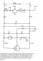
Here is a simplified diagram showing how a 5 hp RPC can be built. This shows a 40- amp single phase circuit however it will work just fine on a 30 amp circuit. I use a 40 amp circuit so I can run about 8 hp total from it. 30 amps will get you about 5 or 6 hp total load.
 

Attachments

  • 5 hp RPC.jpg
    5 hp RPC.jpg
    58.3 KB · Views: 2,444
Thanks for the white rogers reference. I found some additional info on their site and their catalog page: http://www.white-rodgers.com/wrdhom/pdfs/06_Cat_pages/Cat_06_pg0112.pdf

I have a better understanding what this type of relay does, now. Anyone ever dissect one to see how the insides work?

Is it worth buying multiple small run caps for balancing instead of guessing at the right value? The motor I have is German, but made for US voltage and frequency. I'm not sure if that will make a difference in balancing based on the 12-16 uF per HP rule of thumb.
 
What 12-16 mfd per hp rule of thumb? The total for both phases will be more like 35 to 40 mfd per hp.
I buy 40 mfd caps and a couple of extra 20 mfds.

For example: if you think the target will be 80 mfd, you can use one 40 and one 20 to get 60 or you can use two 40's to get 80 or you can use two 40's and one 20 to get 100. You might need a 10 but I never have.

the nmbers we use are based on early and lathe NEMA motors before the high efficiency stuff. Your German motor will definitely be different so who knows what you will need.

Contact me if you need the connection diagram for the converter I posted the ladder diagram for.

Bruce Norton
 
The Hanrahan article here: http://www.metalwebnews.com/howto/ph-conv/ph-conv.html stated that 12-16 mFd/HP would get close to the capacitance for each leg, and he was using a similar sized motor. I double checked mine, and it's actually 5.3 HP. Based on that, I was figuring around 80 mFd each, but using multiple smaller caps is probably a safer bet. It sounds like the level of balancing may be more important for the potential relay than the milling machine. However, I may as well do it right and be better able to run other machines in the future.

I'll start another thread on the European motor. I don't know if it's high efficiency, but it's new enough to be half the size and over twice the HP of the old motors on the mill.

Bruce, if you can PM me the wiring diagram you used, that would be great. I understand things better in a mechanical format. I tried to teach myself ladder logic from some websites a while back, and never got it well enough to create my own working programs. I'll send you an email address if needed. Thanks.


Back
Top