What's new
What's new

Dual Idler 3hp/10hp RPC - Still Learning...

BadDog

Stainless
Joined
Mar 27, 2006
Location
Phoenix, AZ
Ok, first off, I lucked up on a (seemingly so far) very nice 10hp Baldor Industrial "Inverter Duty" motor. This is a sealed case motor, like I want in 2hp for my Grinder. But in any case, the bearings are smooth as silk, and I got it for less than $50.

So, please comment as needed on my general statements. If I'm wrong, please correct/explain in common terms as I am by no means an electrician.

So, after reading quite a bit, and building on what I (hope I) learned with my first 3hp RPC, and trying to merge ToolNuts sketch (below) with my (hopefully) growing understanding, this is what I'm coming to (think I) understand...

Step 1:

Starting with my current functional 3hp GE motor based RPC. I first need to expand my small junction block for a larger "break out" box where it merges with my shop 3ph circuit. All current systems still work, and I can easily build up the extra parts as convenient/necessary.

Step 2:

Modify the contents of this box so that it will now contain additional contactors for controlling which converters are currently "on-line". Since I want to do any combination (3hp, 10hp, 10+3), I need a pair of 3ph contactors there, one for each of the 2 idler circuits.

Add 3 cover switches. 1 to start the 3 hp RPC, 1 to engage the 3hp contactor, and 1 to engage the 10hp contactor.

Now, the "heaters" and run-caps would go behind the relay/contactors so that each is used only when the specific idler is in use. Likewise each load motor would have it's own dedicated heaters.

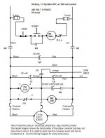
The 1ph 220V T1/T2/N/G tie into the common distribution buss as shown in ToolNuts sketch. These, plus the generated phase from the idler contactors, feed the shop circuit.

Usage:
1) Light the 3hp motor with the Start switch.
2) Engage the 3hp contactor to generate L3 on the common bus.
3) Run any of the small shop machines (ranging from 1 to 2 hp.
4) If I want to run my 7.5hp lathe, throw the switch to engage the 10hp contactor and light the big idler. No start circuit needed because I have L3 from the 3hp Idler. The 3hp switch can be left on or not, probably off since the 10hp should run things just fine for my needs. Turning it off requires both switching the "Start" and "3hp" to "off. But if I need to start the 7.5 on max rpm with a heavy load (chucks/part), then may need both.
5) Shut down is as simple as placing all switches in off position.

Obvious improvements are possible with more complex circuits, but this seems the simple first steps.

attachment.php
 
Now just to separate these from the main "test of understanding", I have some specific questions.

1) I found some surplus "Furnace" contactors. Is there an on-line source for information about them? Specifically, wiring diagrams. The 3ph part is clear enough. And the smaller 2 side terminals are presumably for 110V low amp switching current? But a couple have extra switches/contactors on the side that are controlled by the mechanical relay closing strap(?). Not sure what those would be?

2) 3 of these are rated 7.5hp. They are "Furnace" brand and very simple. But one is GE 10 hp and it looks quite different. More "sealed up in a box". I was told that this probably had an "integrated heater". But I see no indication of it being anything but a contactor. They are Furnas 42BE35AJ106 and GE CR153 respectively. The rest of the GE number was illegible.

3) Frankly, I wouldn't know a "heater" if I saw one. What am I looking for that would identify one appropriate for my needs. I've got access to a pretty good lot of this type of stuff at very low cost. This is mostly AC and other drive systems that were removed during rework/upgrades. But it's basically a "scrap pile" and there is no technical help, so I need to know how to find and identify what I need on my own.

4) Advice for easy visual identification of bad components (can't really test it there) would be handy if possible. Any tell-tale signs to look for?

Any help appreciated. I know this is not rocket science, and I'm not as generally clueless as I may seem. But I just have no experience with this type of electrical work. Thank you for any help you may care to offer...
 
But a couple have extra switches/contactors on the side that are controlled by the mechanical relay closing strap(?). Not sure what those would be?

auxiliary contacts i.e. open or close with main contacts to operate something along with main.....such as a pilot light or some other "thing is on confirmation"

heater.jpg


heater is a device that heats up depending on amount of current in a line
if it gets too hot it temporarily melts letting a ratchet open the circuit
 
Thanks WB, I guess I have seen those, and I have them on some of my existing circuits (came with "load box"(?) mounted on some of my machines). But I always just called them "breakers", though they have a vertical button rather than a toggle. I guess I always assumed when I read "heater" that they were something entirely different.
 
Nobody else has anything to offer? Or just nobody "in the know" reading on Sundays?

Well, anyway, tomorrow I'm going back to the surplus to look for some "heaters". My current 3hp doesn't even have any, but I want to improve that. So, what does one look for in sizing a heater? Based on idler's max amp? Or (seems more important), the load motors max amp? And presumably you don't need the startup "in rush" value, but rather the max HP load current limits. Also makes since (to me) the whole point of a "heater" is that normal startup type spikes don't pop the breaker, but sustained over current will.

So, I need a 3 pole heater rated for 1.5-2 hp running on my 3hp, and one rated for 7.5hp on my 10hp circuit (both @ 220V) .

Also, anyone care to comment on the use of 7.5hp rated contactors with this 10hp idler? Again, seeing as how the load is 7.5hp, that seems to be the controlling factor.

Now, if I can just get lucky tomorrow and get some nice lights (for those aux relays) and big mushroom switches along with a variety of run caps and of course, the heaters. Maybe even a nice NEMA control box to hold it all.

____

Oh, and one more question. Is there any problem with mounting these Baldor idlers in a vertical shaft mode?

I'm thinking of making a frame that looks sorta like a classic dolly. 10hp vertical on bottom (down low to stabilize), with the 3hp mounted vertical right above it. The current 3hp starter circuit and caps will stay in it's very nicely sized (not much extra room) controller box right beside it. And another (to be found) controller box housing the main bus, relays, heaters, and 10hp caps tight below that, next to the 10 hp motor. With offset casters situated right below the boxes (all on angle iron frame) and a convenient handle over the top box, it should be a nice compact arrangement with minimal floor space requirements. I can rock it back on the wheels to move (rarely used stuff will be behind it where I plan to station it) for whatever reason.

And for a general FYI, the main shop 3ph circuit is nothing but hard conduit with a number of 50A plugs, all with matching phase. My current (and new) RPC have a plug the can be inserted in any socket at any location to make it "live". This also lets me plug my 2hp VFD (which has the same output plug) in to power the circuit if needed. Very flexible and convenient for lots of reasons, even though some will balk at powering from plug TO receptacle. <shrug> Unfortunately, I wired it figuring for a max of 3 hp or so. I'll have to check the charts, but I think I'm going to need to rewire it with heavier gage (#8?) for the 7.5hp current load. Oh well...
 
Hmmm, hard to believe nobody has an opinion on this. Have I touched on a sore subject? Am I asking something that's been beat to death and covered to the limits of understanding, and just to stupid to find the trail?

The lathe is home, and the only thing between me and using it is a bit of cleaning and building the RPC. I *think* I have all the primary components to build it, assuming I understand HOW to build it. I've got a selection 7.5 and 10 hp contactors, but need specs on them. For instance, I see nothing denoting trigger voltage. Is it 110V or 24V or ?. I assume that is on a spec sheet, but searching on the net yields nothing but sources to buy them and the same info listed on the tags. I also got a bunch of the "big light" and "mushroom" switches from a big control panel at the scrapper. But it looks like they are all momentary non-latching switches, which means I'll need to provide my own latching relay. Depending on the trigger voltage, I suppose it might be possible to latch it with one of the main relays own output lines.? And I couldn't find any heaters of anywhere near the appropriate size. So I suppose I'll be researching online for some sources.

Can someone please throw me a bone and at least either shoot me down or confirm that I am at least MAYBE somewhere in the vicinity of the right track?
 
Oh, forgot one thing. I called Baldor about mounting them vertically. Turns out that for a load motor, vertical axis is ok ONLY if it has a "locked bearing" (techs words). He looked up my 10hp HE and verified it was rated for vertical. But my 7.5 hp SE motor is not. Huh, who knew? Not me. However, as an idler, he says it should not be an issue, but recommended output shaft down due to the bearing orientation. <shrug> Works for my plans, so I didn't push the issue...
 
I see nothing denoting trigger voltage. Is it 110V or 24V or ?.

most every starter i've seen has it's coil voltage stated
look closer

, which means I'll need to provide my own latching relay.

thats one of the things the auxillary contacts on the starters are used for

not sure why the "EE types" have not settled in on this discussion
there funny somtimes

i think your on the right track here
all you need is a means of turning the big motor on and off and some overload protection
you can do that with the manuel starter i pictured in my earliest post

your used motor contactors will do that also with the properly sized heaters
 
Bad Dog,

Step one: get a magnetic motor starter, which is a contactor plus overload relay, and learn how to wire up a three wire control using a Normally open Start and a Normally Closed Stop momentary push buttons. This is the basis of the phase converter I suggested. You are far from being ready to start wiring a high amperage circuit, so practice some.

On the magnetic starter you will find a power section consisting of the input terminals (L1, L2 and L3) and the output terminals (T1,T2, and T3) between these terminals are the main contacts which are normally open.
The contacts are opened and closed by the coil and moveable armature (think of a solenoid). When the coil in energized, the contacts close. The coil will have a voltage rating such as 120 volts, 240 volts, 208 volts or maybe 24 volts. There will be two terminals on the coil
The coil is held engerized by a seal-in circuit (do not call it a latch-in as a latching relay is another creature altogether). This seal in circuit utilizes a set of normally open contacts operated by the same coil. These are usually a set of auxillary contacts built into the starter on fastened onto the side of it. On Allen Bradley and on Square D starters these contacts are labled 2 and 3.
An overload relay is connected to T1, T2, and T3. If it is the melting alloy type, it will have heater elements that heat a low temperature alloy which allows the overload relay to trip on overloads. The overload relay is equipped with a set of normally closed contacts which must be wired in series with the coil. when the overload relay trips, these contacts open and break the control circuit to the starter coil.

You MUST understand how these circuits work before you start wiring a Phase Converter containing contactors or starters. You must be able to troubleshoot them when they do not work so learn now before you have a high amp phase converter wired up.

Look at the simplified diagram for a 7.5 hp RPC attached here. The top row shows the controls for the magnetic contactor. A short pair of parallel lines with M1 beside it depicts a normally open contact in contacor M1.

I do not have time to post any more so maybe this is a starting point for you to get some practice.

Bruce Norton
 

Attachments

  • 7.5 hp RPC.jpg
    7.5 hp RPC.jpg
    63.4 KB · Views: 12,851
You MUST understand how these circuits work before you start wiring a Phase Converter containing contactors or starters. You must be able to troubleshoot them when they do not work so learn now before you have a high amp phase converter wired up.

kinda thought this might be the rub

and that is a big issue

if you don't really understand the basics
building a system could be dangerous
 
Thanks for the input guys. And sorry about the bad terminology (re. "latching").

I do understand the mechanics of how coil actuated relay/contactors, switches and so on work. I also understand how the "heaters" work (typically alloy melts, releases ratchet, spring opens contacts). And, I have no experience with them, but if I understand correctly, magnetic starters just mix all this up into one (slightly) simplified and more compact package.

In any case, I know I have to spend more time pondering over this and improving my understanding before I start actually doing anything. I mainly just wanted to make sure I wasn't completely missing the "big picture" (how to create a staged dual idler RPC) before spending a lot of time on the details. Again, much thanks for the input...
 
Well, of course you were right, the trigger voltage is on them, just not on the main relay info print. It was around on the back side near the coil itself. And just my luck, all of the 3 pole relays are 24V triggered. I remember some 24V transformers in those boxes and thinking I should probably take one. Oh well...
 
what size(hp rating) are they
i'll trade you for a 110 volt coil starters if you want
i can size the heaters too if you tell me what size motor your going to run
 
Most state 7.5hp at 220V/3ph, but I have a couple of 10hp as well. Some open contactor, some concealed with a button in the middle. Some with secondary relays on the side. But all of the 3ph models say 24V...

I would love to do some swapping, but really not worth it I think. I can pick up a 110V/24V transformer easily enough from several sources, probably for well less than the cost of shipping (likely free even). And the 24V will likely play more nicely with the switches I got too. Obviously I need to check them, but they came from the same component boxes, so I'll bet they are 24V too.

Man, this week stinks for trying to get anything done. Work and family taking ALL my free time and I can't seem to get my head on straight. This weekend is hopefully going to get a bit better and I plan to sit down and spend some more time going over this stuff in detail...
 
Oh, and in my hurry earlier, I forgot to mention the main reason I'm hesitant to do a swap. These are scrap yard/surplus and I have no way to even test them without getting a 24V xformer, at which point I might as well use them. However, you have been one of very few who even bothered to try to help at all. So if you want one or two (once I'm sure of what I'm going to use), I'll send it for the cost of shipping. Thanks for offering what you could.
 
Hey, WB, interested in that contactor?

Ok, I've got a 24V transformer (the one Doug posted about in fact). Probably over kill for my needs, but I think I still have a problem.

The design I'm going for would allow me to add and remove idlers at will. So I would have 3/10/13 hp options. That will require a minimum of 2 contactors with "seal-in" (as opposed to "latching" which I mistakenly applied from electronics) circuits. If I follow correctly, seems there is a problem using the transformer.

If the coil voltage were the same as an output leg, I could just back-feed one output to the coil so that once closed, it would stay closed until loss of power to the contactor ("off" or power outage) at which time it would stay open till closed again. So a simple NO momentary would close (and seal-in) it, and a NC momentary in the back-fed coil leg would be enough to open it.

But the only way I can see this working (based on my ideal panel operation) is with a 24V xformer for every contactor (2 in my case). That surely doesn't seem right, so what am I missing? Not bad for my situation, but I can't imagine that's how it would be done for panels full of contactors.

I guess I could just use toggle switches rather than momentaries on the 24V lines to each relay coil, but then that still presents a problem with a momentary NC "e-stop" button. I do have a single 110V relay (coil and primary) that could be used to control the 24V transformer input. And that relay could be "self seal-in" wired with the circuit broken by the e-stop momentary, thus dropping out the 24V xformer. Still, far from ideal I think...
 
BadDog,

You can use one transformer and as many contactors as the transformer will support.
Forget about "backfeeding" and look at the diagram I posted showing you how to connect a three wire control to a contactor. All you do is wire the contactor controls in parallel. The contactor contacts are not interconnected. You can have 24 volts on the auxillary contacts and 240 volts on the main contacts with no problem. You may have to remove any factory installed jumpers but that is all. You do not backfeed anything here. You have the normally open auxillary contacts, one on each contactor, wired in parallel with the START switch for that contactor. When the START is pushed, the auxillary contacts close and provide a path parallel to the START. When the START is released, the coil continues to be fed throught the auxillary contacts until the STOP is pushed. This is the "seal-in" circuit I mentioned earlier.

Get a contactor / starter and a normally closed push button and a normally open push button and wire up the control circuit to the contactor and learn how it works.

I will post a wiring diagram for the schematic of the multiple idler as soon as I have time to draw it.
 
I would love a diagram, maybe that will clear up what I'm missing. Thank you very much for taking the time to help...

However, it seems this may be a another terminology problem.

I am using your ladder diagram (assuming I understand correctly), but modified to eliminate the start circuit as I already have that working on the 3hp, which will then act as a starter for the second 10hp motor. So, I'm basically taking your top rung as the relay control. And that M1 contactor in parallel to the start button, both feeding the M1 coil, is what I was calling "back feeding". I.E. taking the output of the contactor and feeding the coil to hold it closed (what I originally called "electrically latched" from electronics terminology). Sorry if that's not correct terminology, but I think we are talking the same thing.

So seems the mod would go something like this.

The NO start button provides 110V to the 24V xformer, which closes the (NO) M1 coil through the NC stop button. M1 closed feeds 110V to the 24V xformer via the aux (or primary) contact and feeds 220V T1 and T2 into the rest of the circuit. Pushing the NC stop button breaks that 24V feed to M1 coil, and thus cuts power to everything. End of rung 1.

There is a M2 NO contactor that connects the 3hp RPC to the distribution bus. It has a start button that connects 24V to the M2 coil and it's aux contact holds 24V there until broken by 3hp Stop button or loss of power (primary stop or line).

The 3hp RPC is complete and unmodified except to mod for remote (external panel) switch for start/stop.

The 10hp RPC has an M3 NO contactor that works just like the 3hp RPC. The only difference is that it won't start unless the 3hp is running. Ideally, this would series in the aux contact from M2 so that M3 won't close unless M2 is closed. But it will stay closed (using it's own aux contact) even if M2 drops out.

Sorry for the ramble, but just checking my understanding. I probably missed key points and used the wrong terminology, plus I haven't sketched it out yet, but it seems about right...
 
BadDog,

You are making lots of progress on the converter concept.

It is simplier than you are now thinking but I can describe it in words. A ladder diagram will be much better so I will make one as soon as I have time to do it electronically. I have the controls sketched out and they are simple but hard to describe in words.

Basically, I see one improvement to you concept. Put a power on/off disconnecting device so you can shut all power off to the converter and the 3 phase panel. This can be one of several types such as a main breaker in the 3 phase panel, a two pole, 60 amp knife disconnect switch or a magnetic contactor as I had in the orginal block diagram. This is needed so you can shut off all power to the three phase panel and lines to the tools.

Put the transformer first in your control scheme. It will stay energized anytime the main power disconneting device is ON. From the 24 volt side, you just draw a ladder diagram with the contol circuits in parallel. One leg of the 24 volt will need to be grounded near the transformer. The 3 hp RPC can be built simplier than my 7-1/2 hp. You can operate the start capacitor directly from the Steveco potential relay and eliminate the start contactor. I will need to post you a diagram for connecting this. There are no modifications required to the potential relay either.

Here is a description of the control circuit ladder diagram until I have time to draw it.

do the 3 hp the same as shown on my 7-1/2 hp diagram This contactor is M1

between the 3 hp Start and Contactor (M1), connect a wire to feed the START button on the 10 hp start circuit. From the Start, connect to the STOP, then the Contactor Coil (M2), the overload normally closed contacts, and to the 24 volt leg on the right side of your diagram. Go back to the 24 volt leg on the left side of your diagram and draw a line to M2 normally open auxillary contacts. From the contacts connect to the wire between the Start and the Stop for the 10 hp idler. This puts m2 n.o. in parallel with the 10 hp Start button but it is fed directly from the 24 volt left leg.

You must start the 3 hp first then start the 10 hp but you can shut of either and the other will continue to run.

Note you now need only two contacors, M1 for the 3 hp and M2 for the 10 hp. Also note the Start button must come before the STOP on the 10 hp. This is different from the convention I normally use. The 7-1/2 hp diagram shows the STOP first then the START.

Happy tinkering
 
BadDog;

I have the controls section drawn but the file is 126 KB and is too large to post here. I do not have the RPCs drawn in yet. If you will send me a private message and include you email address, I will send the excel file to you.

Bruce Norton
Kingsport, Tn


Back
Top