Hi all,
I think this is the right forum for this question. I have a woodworking machine, a shaper, which I use to run full length 1 3/8" delrin rod through. I cut a flat on it, then run in again to cut a small groove on the other side. Then I bring them to the shop and finish the machining on machine tools.
It's an Italian machine set up for US 220-240 single phase. It has a separate power feed, and when running the stock, the capacitor in the power feed shorted out. Since the machine itself was coming up to rpm very slowly, I checked the capacitors in the elecrical panel before ordering the power feed capacitor and found both capacitors in the shaper to be in bad shape.
After installing them, everything worked for a short while, then the main machine stopped at about the time I smelled the motor burning. The power feed continues to operate fine.

Here are some pictures of the original weird capacitor setup, for your viewing enjoyment. The one on the left, by itself, I replaced in the power feed, which still works fine. Before I ordered the replacement, I checked the ones in the main machine - which was starting off very sluggishly, but it did run. What I saw is that one had the huge drool of hard grey stuff, so I decided to replace the two of them as well. STUPID! I should have waited until I ran the plastic first.
The smaller one of the two that are connected has 4 separate terminals coming out of the epoxy top, and has two voltages marked on it. It says 40 uF AC 400V B then has a dotted line and under it is says 40uF 450v C.
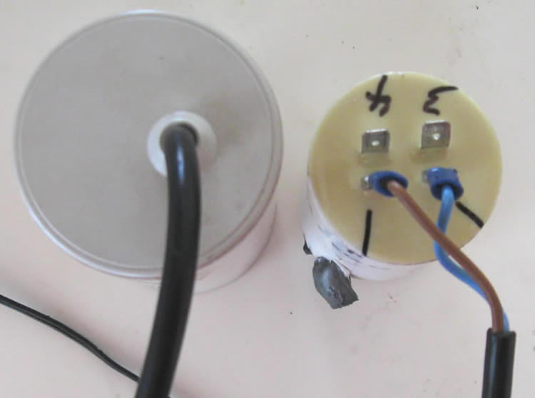
After cooking the motor (which I assume I did since it no longer will run), I discovered that the large capacitor had a cap on it after I dropped it and it popped off. This is what I found inside. The relay inside of the big one has a symbol which looks to me like a normally closed switch, then a dash, then 110v = DC. There is something to the left of the big white rectangular thing which got hot enough to cause the plastic cap to discolor and cause a bulge in the plastic case. Looks like what resistors and diodes look like - but it is mostly burried in the epoxy, so I can't see any markings. The round blue one is a capacitor - 100uF 160v.

Does anyone have an idea what this stuff does? Does it replace the centrifugal cutout switch normally found in US made single phase motors?
I am hoping the motor company can just tell me where to put the capacitors, and add a cut out switch to the motor (assuming that's what the above electronics are for) so I don't have to mess with this any more. I have never had any luck with motor companies, and wish I knew how to test the things myself. Seems like they always mess the motors up - or say they work fine when they don't.
Any help or suggestions would be greatly appreciated. Thank you. I have no wiring diagram, no operators manual, and the machine is no longer imported into the US. Also, the motor has a brake which is working with both the manual switch, and when the "motor on" switch is activated.
Cheers,
Jim
I think this is the right forum for this question. I have a woodworking machine, a shaper, which I use to run full length 1 3/8" delrin rod through. I cut a flat on it, then run in again to cut a small groove on the other side. Then I bring them to the shop and finish the machining on machine tools.
It's an Italian machine set up for US 220-240 single phase. It has a separate power feed, and when running the stock, the capacitor in the power feed shorted out. Since the machine itself was coming up to rpm very slowly, I checked the capacitors in the elecrical panel before ordering the power feed capacitor and found both capacitors in the shaper to be in bad shape.
After installing them, everything worked for a short while, then the main machine stopped at about the time I smelled the motor burning. The power feed continues to operate fine.
Here are some pictures of the original weird capacitor setup, for your viewing enjoyment. The one on the left, by itself, I replaced in the power feed, which still works fine. Before I ordered the replacement, I checked the ones in the main machine - which was starting off very sluggishly, but it did run. What I saw is that one had the huge drool of hard grey stuff, so I decided to replace the two of them as well. STUPID! I should have waited until I ran the plastic first.
The smaller one of the two that are connected has 4 separate terminals coming out of the epoxy top, and has two voltages marked on it. It says 40 uF AC 400V B then has a dotted line and under it is says 40uF 450v C.
After cooking the motor (which I assume I did since it no longer will run), I discovered that the large capacitor had a cap on it after I dropped it and it popped off. This is what I found inside. The relay inside of the big one has a symbol which looks to me like a normally closed switch, then a dash, then 110v = DC. There is something to the left of the big white rectangular thing which got hot enough to cause the plastic cap to discolor and cause a bulge in the plastic case. Looks like what resistors and diodes look like - but it is mostly burried in the epoxy, so I can't see any markings. The round blue one is a capacitor - 100uF 160v.
Does anyone have an idea what this stuff does? Does it replace the centrifugal cutout switch normally found in US made single phase motors?
I am hoping the motor company can just tell me where to put the capacitors, and add a cut out switch to the motor (assuming that's what the above electronics are for) so I don't have to mess with this any more. I have never had any luck with motor companies, and wish I knew how to test the things myself. Seems like they always mess the motors up - or say they work fine when they don't.
Any help or suggestions would be greatly appreciated. Thank you. I have no wiring diagram, no operators manual, and the machine is no longer imported into the US. Also, the motor has a brake which is working with both the manual switch, and when the "motor on" switch is activated.
Cheers,
Jim
Last edited: