What's new
What's new

Please Help With Hitachi VFD

mbogo375

Aluminum
Joined
Jul 6, 2008
Location
SE Georgia
First let me say that I am very "electrically challenged" :o, so please keep in mind that I am below the entry level of knowledge here.

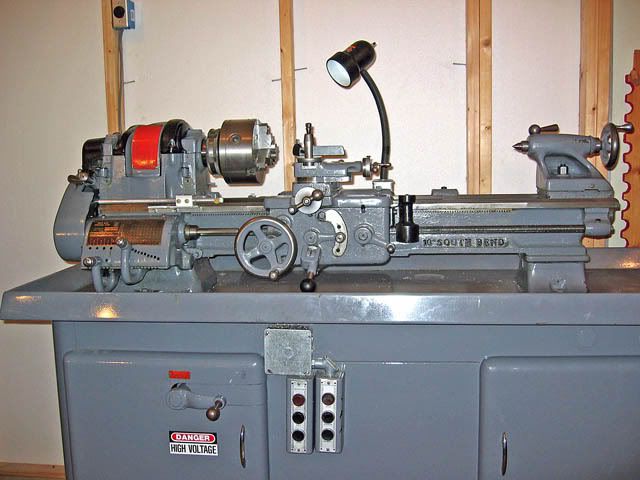
I am trying to get my new-to-me South Bend Heavy10 running, and I am having a problem getting it to run on the high speed winding. Actually it won't run at all, unless I wire it to the low speed side (it is a two speed, 1HP motor). I have only been wiring to one side or the other, not both.

When trying to get the high speed winding to work, it always gives an "over current event" error message when I attempt to start the motor. I assume that the motor is pulling more current than the default setting on the VFD :confused:. Can the VFD be reset to allow for start-up, or is this not the problem?

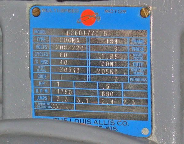
The VFD is a Hitachi SJ200. Input is 220 single phase. I am attaching a photo of the plate on the motor.

Thanks for your help. If I get the motor running I might have a few more questions on how to wire in a remote forward-off-reverse switch, and potentiometer.

Jim

SouthBend10L011copy2.jpg
 
You'll want to wire it for high speed.

Just wire the motor in the high speed configuration, and use the VFD to adjust the speed. Make sure you have the VFD's current limit setting set for the high speed current of 3.3 amps. If you left that set for 2.3 or 2.4 it will give you an overcurrent message. It's either that or you have it wired wrong, and it's shorted out :eek: in which case it could fry the VFD!!!! Is the motor wired directly to the VFD like it's supposed to be, or do you have a speed switch in line still?? If you still have the speed switch, are you throwing that while the motor is spinning??? That's also a BIG NO NO, it can fry it! You set the switch to high speed, and use the buttons on the VFD to start the motor.

Did you go through and set the output voltage, and current information like you're supposed to, or are all the settings default??? Another thing is if you set the VFD's number of poles for the low speed setting, it might cause it to give problems. You should set the number of poles to 4 for the high speed winding, instead of 8 for the low speed.

If you could post a wiring diagram from the motor, that would help so we can confirm that the motor is wired properly for high speed. If you have the current (3.3 amps), number of poles (4), and voltage (220v) set properly, the motor should run in high speed mode. If that's all good, the wiring may be wrong, or the motor is bad, or there's too much of a load on the motor to start that quickly. Try taking the belt off the motor, and see if it starts if you have everything set properly.
 
Thanks for the reply.

Yes, I tried wiring the motor directly to the high speed winding only (confirmed by the fact that the other three wires work with the low speed winding). I was using the keypad controls to control the motor, and go through the setup.. The setup the default frequency was 60Hz, the default voltage was 200-230, and the default amperage was 5.0, so I did not change them. The number of poles was defaulted at 4, so since I did not know the correct number of poles I did not change that either.

Unfortunately, the wiring diagram apparently was on the lathe cabinet base door, and is mostly missing and totally unreadable.

The drive belt for the lathe was not under tension, so the motor was not driving anything other than the motor pulley unit.

Jim

Just wire the motor in the high speed configuration, and use the VFD to adjust the speed. Make sure you have the VFD's current limit setting set for the high speed current of 3.3 amps. If you left that set for 2.3 or 2.4 it will give you an overcurrent message. It's either that or you have it wired wrong, and it's shorted out :eek: in which case it could fry the VFD!!!! Is the motor wired directly to the VFD like it's supposed to be, or do you have a speed switch in line still?? If you still have the speed switch, are you throwing that while the motor is spinning??? That's also a BIG NO NO, it can fry it! You set the switch to high speed, and use the buttons on the VFD to start the motor.

Did you go through and set the output voltage, and current information like you're supposed to, or are all the settings default??? Another thing is if you set the VFD's number of poles for the low speed setting, it might cause it to give problems. You should set the number of poles to 4 for the high speed winding, instead of 8 for the low speed.

If you could post a wiring diagram from the motor, that would help so we can confirm that the motor is wired properly for high speed. If you have the current (3.3 amps), number of poles (4), and voltage (220v) set properly, the motor should run in high speed mode. If that's all good, the wiring may be wrong, or the motor is bad, or there's too much of a load on the motor to start that quickly. Try taking the belt off the motor, and see if it starts if you have everything set properly.
 
Well, just switching to the other 3 terminals probably isn't right.

You're going to have to find a wiring diagram, or find somebody that knows how to sort out a 2 speed 3 phase motor with no schematic. I can tell you that just switching the wires to another set of terminals probably isn't the correct way to configure the other speed. The motor SHOULD spin using those settings if the high speed wiring is correct and the motor is good. It sounds like you've got it wired wrong to me.

If there was a speed switch, and you remember how that was hooked up, you could try sorting out the motor that way. All you'd need it a multimeter with a continuity test function (preferably one that beeps), or a continuity test light. What you'd do is set the switch in the high speed position, and test for continuity from the line input wires to the wires that go to the motor. You'd do this WITHOUT POWER connected, the VFD, and the motor UNHOOKED. You'll have the 3 wires that are the line in, and each one will have continuity to 1 of 3 of the wires that go to the motor. Find those 3 wires on the motor side, and you'll have the proper wires to connect to the VFD. :cheers:

Are you sure there's no schematic on the lid of the housing for the motor's electrical connection or elsewhere on the motor??? There's usually a schematic somewhere on the motor itself.

Actually, I had an electrician helping with the initial hookup. He was the one who determined which three wires went to the high speed wiring, and which went to the low speed winding. He was not familiar with the Hitachi VFD, and did not know how to program it. He also could not find a wiring diagram. That brought me to my current situation ;).

Jim
 
Some thoughts on SJ 200 Hitachi.
In single phase mode you will need to attach incoming main power to L1 and L3 input terminals. L3 on Hitachi is confusing since it is often labeled "common".
The SJ 200 will need to be rated for 7 amps output per phase at 220 volts ac. This is due to 50% derating when the frequency drive is run off single phase input.
You can program a very long power up slope to reach 60 HZ output. That may reduce tendency for unit to drop out due to overcurrent.
Post pics of Hitachi if possible
jh
 
One remote possibility is the acceleration parameter is set to fast.

Default on the sj200 is 10.0 seconds. That should be slow enough to not cause an overcurrent on either fast or slow mode of that motor.
Parameter F002 is what sets the acceleration curve. F003 is deceleration.
F003 should be set the same or it could also cause an overcurrent alarm while changing speeds.
It could be the motor is bad too.

Theres plenty of us here to help with the remote speed control etc when you get to that point.
 
The SJ 200s DO NOT need to be derated.

They run fine off single phase or 3 phase, and no derating necessary on drives 3hp and under. Also, it doesn't matter whether you have the power connected to L1 and L3, or L1 and L2, or L2, and L3. What you DON'T WANT is a NEUTRAL connected to one of the L terminals. That would cause problems, but if the VFD is working, it's more than likely wired right. It would be a good idea to double check though. It SHOULD be wired with single phase hots on L1, and L3, with NOTHING on L2. If you see a wire on all 3 terminals, that's a problem. It will work so long as hot leads are going to any combination of the L terminals, because each terminal is connected to two identical diodes. :cheers:
 
You're going to have to find a wiring diagram, or find somebody that knows how to sort out a 2 speed 3 phase motor with no schematic. I can tell you that just switching the wires to another set of terminals probably isn't the correct way to configure the other speed. The motor SHOULD spin using those settings if the high speed wiring is correct and the motor is good. It sounds like you've got it wired wrong to me.

...snip

Are you sure there's no schematic on the lid of the housing for the motor's electrical connection or elsewhere on the motor??? There's usually a schematic somewhere on the motor itself.
Actually, if you look at that nameplate, it is a single voltage 2 speed 2 winding motor, so it should have just 6 leads, and the "other" 3 should be the high speed winding.

mbogo375,
I'm not so sure about your statement "the default amperage is 5.0". There are two ratings on a VFD. The maximum power the drive is rated for, which shows up in programming sometimes because the mfr sets in in firmware, then there is the motor nameplate amps, which you must enter yourself. That step is very important because that is providing the overload setting of the VFD to protect your motor. In this case that should be in Function B012.

Therein might be the problem. The only SJ200 that has a default setting of 5.0A is a 1.1kW IEC-only version, not intended for sale in the US. That means all of its default settings are going to be based on 50Hz. So if it is, your V/Hz ratio is going to be wrong and will leave you with insufficient torque to accelerate. When you are on Low speed, the motor HP is cut in half, so the VFD is sufficiently over-sized and can make up for it by pumping out more current (although you are stressing that motor). When you switch to High speed, the torque difference makes it too weak to accelerate, it slips more and overloads, even though you have the OL setting at maximum. So you are in danger of severely damaging that motor, even if you just keep using it like you are now. If that is the case, change settings A003 and A004 to 60 Hz, that should take care of it. Then also make sure B013 is set to 3.3A (if you are successful in getting the High Speed windings to work) and B013 is set to 01 (it should be).
 
Thanks for all the replies. I just wanted to update the situation.

Today I rewired the VFD to the high speed windings just as I had before, intending to work with the programing. Wonder of wonders, it was working this time :confused:. The only difference was that between the original attempt and this time, I reset all the parameters to the factory default setting yet again (for the third time :crazy:). The only thing I can figure is that between the electrician and myself, somehow a setting got changed before the first attempt to run the motor. When it didn't work at that time, in my attempt to reset the defaults, somehow I missed something. The strange thing is that the motor has worked on the low speed winding the whole time.

In any case it seems to be working as it should now, so the next thing on the agenda is to add a remote forward-off-reverse switch, and a remote speed control. Any suggestions about these items, and wiring, will be greatly appreciated.

I will be out of my shop and away from the computer the rest of today and tomorrow, but will check back on this thread on Sunday.

Once again, THANKS!!!!!! :D

Jim
 
Good to hear.
Don't forgo setting that OL protection parameter for the motor nameplate FLA however (unless you have a separate OL relay) and double check the settings I mentioned above. Even if iot works, you want it working right and protecting your motor.
 
Good to hear.

A good place to get a pot, project box, and buttons is MCM electronics. MAKE SURE you get one of the high quality pots that cost about $10, the cheap ones aren't sealed, and don't survive garage life well. If you want help wiring, selecting parts, and programming, I'm here. :cheers:
 
Here is a hookup diagram for a SJ200 installation on a Bridgeport Milling Machine using the orginal drum switch to control the VFD. You must be certain there are no jumpers between any of the three contacts in the row you use to control the VFD.

Hope this helps.

Bruce Norton
Kingsport, Tn
 

Attachments

  • SJ200.jpg
    SJ200.jpg
    94.2 KB · Views: 11,730
Thanks again to everyone for all the help.

I am now at the point of needing the parts for the controls. It is unlikely that I will be able to get what I need locally, so advice on specific parts, and on where I can get them would be greatly appreciated.

Not knowing what I really need, I have been thinking that mounting the new controls under the lip of the cabinet next to the old controls might provide reasonable access, and a degree of protection for the controls. I may just leave the old controls in place, at least for the present, although I suppose this would be the logical mounting point if the they were removed.

I guess I could even rewire one of the existing three button controls for forward-stop-reverse :confused:, and add a potentiometer to the face plate of the existing wiring box, but I think I would rather have a three position switch instead of buttons. As you can tell, I have no solid opinion one way or the other. Suggestions?

Jim

SouthBend10L015copy2.jpg
 
I'd use the existing controls, and add a pot.

I've got a suggestion on where to buy the potentiometer. I bought mine from MCM electronics, along with the other parts. In your situation, wiring to the existing 3 wire setup would be EXTREMELY EASY! It's a 2k ohm 2 watt, and you want the high quality sealed industrail pot. They cost around $10. http://www.mcmelectronics.com/product/501-0006 . I prefer the anitque pointer style knobs http://www.mcmelectronics.com/product/50-1955 , whatever knob you use will have to be the set screw type because the pot has a round shaft. Of course they discontinued those, but they do have another type of knob that will work http://www.mcmelectronics.com/product/50-1935 . Anyways wiring the buttons to the VFD is dead simple. There's only one little hitch, you'd have to replace one button with a switch for forward/reverse. You program it for 3 wire control, assign the terminals you want to use to the proper functions, wire the proper buttons to the proper terminals. One button will be the start button, it will tell the motor to spin in whatever direction the fwd/rev switch is set to. The other button will be the stop button, which obviously stops the motor. That's the way I'd do it, but it's up to you.

If you want to do switches, that's possible too. You'd have a switch to run the motor in the forward direction, another for reverse, and the pot. The forward switch overrides the reverse, and if you get confused, it's easy to flip the wrong switch in an emergency. Then you have to turn them BOTH off in order to get the motor to stop. Where you can put a big red button on there to stop in a panic situation with 3 wire control. You can do a big red button with the switches too, but it either needs to latch open, or you have to reset the VFD from the front pannel, OR you need a reset button rigged up. Whatever method you decide, I HIGHLY recommend a big red (oh shit) button. :cheers:
 
If you use switches it is not complicated. just use a single pole, double throw, three position toggle switch with the center position as OFF. I wire them such that Up is forward and center is OFF, down is reverse. Just like the drum switch shown in the diagram I posted. You will have none of the problems Junkyard mentions.

Personally, I would use as much of the orginal controls as possible. It is very easy to do. I prefer momentary push buttons and three wire control as this will not automatically restart after a power outage.
 
I prefer momentary push buttons and three wire control as this will not automatically restart after a power outage.

It doesn't matter what switches you use, a properly setup VFD will not autostart after a power outage no matter where the switches are set or what switches are used.

As far as a POTs goes, I have used pots from Radio Shack without issue.
 
Duh!

If you use switches it is not complicated. just use a single pole, double throw, three position toggle switch with the center position as OFF. I wire them such that Up is forward and center is OFF, down is reverse. Just like the drum switch shown in the diagram I posted. You will have none of the problems Junkyard mentions.

Personally, I would use as much of the orginal controls as possible. It is very easy to do. I prefer momentary push buttons and three wire control as this will not automatically restart after a power outage.


OMG, I really can't beleive I didn't suggest doing it that way! I've seen things wired that way That makes a LOT more sense than 2 switches, but it's still somewhat dangerous in a panic situation. People have a tendancy to throw switches too far when panic situations arise. I'd put a big red button it either way. That gigantic red button on my VFD is IDEAL, it's 3" in diameter. :cheers:
 
Latest update :o. I have exhausted the local possibilities (an electrical supply place, a machine supply, Lowe's, and Radio Shack). There are NO three phase switches, or 220V potentiometers to be had period.

Would anyone be so kind as to suggest a SPECIFIC Part NUMBER for a three position toggle and a potentiometer from somewhere like MSC http://www1.mscdirect.com/ ? There are so many similar switches there that, as an electrical newbie, it makes my head spin :crazy:.

Thanks,
Jim


Back
Top