What's new
What's new

Help Me Wire This With Photos!

Nitromahn

Aluminum
Joined
Sep 11, 2008
Location
Bethel, Alaska USA
Ok, I had an electrician over here for five hours gratis, he left extremely frustrated. He could only get the motor to run in the forward direction, anything else would pop the breakers. I gave him all the diagrams I had copied from the searches here, and others elsewhere. He swears both the motor and switch were wired correctly. He finally wired the motor to run, but only in the forward direction. He thinks it has to be "something unseen". Meaning the switch could be bad or even the motor. BUT it is a factory new motor soo......

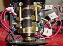
The first pic is the motor as wired to run in the forward position. The only wires connected from the switch are 1 and 2 and you can see the labels at the top and bottom. The two pink wires heading off to the right out of the photo are 5 and 8, both capped off until we (Mr. Sparky and me), get an answer.

The second pic is the switch in the off position. Cast copper conductors in this 1926 Westinghouse!
The dark green (or black), wire comes in and runs off to the left to connect at the bottom of the bank of posts.
The light green runs up the right side to the top;you can see the yellow connector.
You can see where the white goes.

Third pic is the forward position.

Fourth pic is (drum-roll), the reverse position.

Ok boys and girls: tell me what goes where, and do it sssllloooowwwllllyyyy, please. You are dealing with a chemist, not a fellow machinist or sparkician.

This is a 3/4 h.p., 1125rpm, 110v single-phase, split-phase capacitor start, AC motor. It has one hump on the top. Baldor Model CHC3528A.

Good idea Gary.

Quyana.
 

Attachments

  • Forward Motor Wiring.jpg
    Forward Motor Wiring.jpg
    56.2 KB · Views: 7,451
  • Switch Off.jpg
    Switch Off.jpg
    91.7 KB · Views: 1,191
  • Switch Forward.jpg
    Switch Forward.jpg
    93 KB · Views: 724
  • Switch Reverse.jpg
    Switch Reverse.jpg
    88.8 KB · Views: 996
  • Motor Plate.jpg
    Motor Plate.jpg
    71.2 KB · Views: 1,192
I am not going to answer your question. However, it might help who ever is going to if they knew something about your motor. Is capacitor start? Does it two capacitors or one? Maybe a photo of the motor and the data plate. Sorry I can not be of more help but some one will be along soon. Gary P. Hansen
 
First things first 120V or 240V?

For 120V the J wire goes on Post #4, for 240V the J wire goes on post #3

Typing this for the third time now, looking at the switch as pictured. *=switch terminal, ... is just a place keeper, ---- is a connection, | is a connection
*....*
*....*
*....*

*Wire #8 from the motor................. *L2 Line In & L2 From Motor
* Wire from Motor #4 Terminal....... * Wire #5 from the motor
* L1 wire from Motor........................ * L1 from Line In

Continuity Diagram
Off
*8............. *L2 & L2m
*4............. *5
*L1m.......... *L1
FWD
*8----------*L2&L2m
*4----------*5
*L1m--------*L1
REV
*8............. *L2&L2m
..|................|
..|................|
*4............. *5
*L1m--------*L1
You may have to swap wire 8 & 5 on the switch for the motor direction to correspond to the switch nomenclature. Check it all cold with an ohmeter first. Subject to peer review. Hopes this helps.
 
There are several applicable drum switches for a single-phase capacitor start/induction run or capacitor start/capacitor run motor.

The attached one is for a Furnas drum switch, circa 1945, off of my Logan.

The main point is all line conductors are isolated when the drum switch is in the OFF position.

This is shown for low voltage.

This drum switch may be used on high voltage by connecting one end of the start winding to the midpoint of the run winding.

The theory is these dual voltage motors always start on low voltage and run on either low or high voltage, as wired by the owner.
 

Attachments

  • Toshiba_Motor_110.jpg
    Toshiba_Motor_110.jpg
    53.3 KB · Views: 29,132
Okay, I should have been specific about the voltage I intend to use: 110v.

I am going to print that description and diagram, dig out my Fluke and spend some quality face-time with the switch. Maybe have my guy come over to double check what I am doing.
 
OK some general comments. I'm figuring you want to run on 120 volts, that is,
the "low voltage" version of the wiring diagram in your photo.

So here's a picture:

motor_wire.JPG


First off I am thinking your drum switch operates according to figure one in the
picture. One position gives the connections on the right, and the other position
of the handle gives the connections on the left. Obviously in the off position there
are no connections made at all. If these conditions are not true then everything
that follows is completely untrue and won't work.

Now if you look at figure two in the picture this is pretty much what you are trying
to achieve. There's a lot of wiring going on 'under the covers' so to speak but
in the end you want the incoming hot and neutral to basically go to terminals
L1 and L2 respectively. And you want the two wires, wire 5 and wire 8, to pretty
much do what the picture shows, in one rotation wire 8 goes to terminal X (the
center one, it might be 4 in your photo but I could not be sure, so I'm calling
it "X" to prevent confusion), and wire 5 goes to L2.

And in the opposite rotation, wire 5 needs to go to terminal X, and wire 8 goes
to L2. So the comment, 'to reverse rotation swap 5 and 8' is obtained.

I think if you look at figure three in the picture that shows how I would wire the
drum switch. If you mentally fill in the switch contacts you will see that it
gives the desired results. Also it completely disconnects the hot line from
the motor entirely when off, via the bottom-most set of contacts.

I cannot understand why your electrician's wiring smokes on reverse, nor can I
really tell what's going on because of the wires in the motor terminal container
that are bent out of view and are a bit mysterious to me.

I throw this out for comments.

Jim
 
Here you go:
Forward_Motor_Wiring.jpg


Everything you see with the exception of L1 and L2 are the connections inside the motor to the windings as from the factory. The only wires connected to the motor from the switch are L1 and L2 with the arrows. The internal wiring corresponds with the diagram on the metal cover plate, which is the same as the PDF doc S. Wells sent me.

I think I have enough to go on now, I need to check the switch for problems, then call my guy and have him come over to look at this.

Thank you for the time you've invested, I do appreciate it greatly.

Whoops! The two wires bent out of the way are connected at the switch only, and are capped for safety, and are No. 5, and 8. He just put them aside like that until we were able to get things fingered out.
 
Hi There,

I have been looking at your pictures and diagrams and I think
I have a diagram that will work. Please note. I could be very
wrong so check your switch and motor connections with
an Ohm meter and make sure they correspond with this
diagram
!


BaldorMotorDiagramcircuit.jpg


Good Luck!
-Blue Chips-
Webb
 
Hi Webb.
That is the same switching I come up with, but I'm still not sure that is correct on the B phase 5 and 8 lead. I believe 5 on L2 in forward might be correct and 8 on L2 in reverse.
This motor should have a thermal overload having the J wire. To reverse, the B Phase 5 & 8
would swap out on this J wire(brown?) to the thermal and L2... is that correct? If it runs
backwards in forward he can just swap the 5 & 8...
I've looked at it for several hours...Even checked an old 809 WH from 1923 and it's time to
call it a night.

Steve
 
Hi There,

Steve, it is unclear to me whether the "J" lead is connected
to a thermal overload device or is simply a jumper lead.
Usually, the leads from the overload device are labeled "P"
but that is why I put the caveat about checking the leads
with an Ohm meter in my earlier post.

If the "J" lead does indeed comes from a thermal overload
device inside the motor, then it would be best to move it
out to the drum switch but then another "jumper" will have
to be rigged-up to provide continuity from the terminal 4 to
L1.

As to the "B" phase you refer to, I'm not sure what you are
getting at. I think it is a matter of semantics. As you are
aware, leads 5 and 8 are the start winding leads. reversing
their polarity (in relation to L1 and L2) will reverse the direction
the motor will turn when starting. As you surmised, reversing
these leads will correct a motor that "runs backwards" when
forward is selected on the drum switch. This is alluded to at
the end of the diagram.

Good Luck!
-Blue Chips-
Webb
 
"J" looks like a simple jumper (purple wire with partly visible
white wire lable) in the photo above. I cannot see where
it could be diving into the interior of the motor. Seems
like it just connects one terminal to another on the board.

Jim
 
Let me correct myself...Yes, now that I read the left lower part of the print,
the thermal overload is optional. I'm not sure if it has it or not, if not I concure
that it would just be a jumper to L1. As to the start winding, this motor does not have
a cut out switch, rather it has a run-type capacitor permanently connected in series with the start winding. This makes the start winding an auxiliary winding.
I believe this is the correct print for his motor:
http://www.wswells.com/data/prints/baldor_psc_35_wiring.jpg

Steve
 
I wish I could come and give you a hand, as it is difficult to assist in these situations without having the switch right in front of me. I recently replaced the motor and wiring on a large rotisserie oven with a very similar reversing apparatus. Here's where you're going wrong....In order to reverse, you need to swap 5 and 8. So you need two more wires from the motor to the switch.

Procedure:

Run two more wires from motor to switch, label 8W and 5W

We're going to call the wires from inside the motor that are connected at the terminal board connections wires 5M and 8M.

Disconnect #5M wire at motor from board and connect #5M wire to new wire 5W

Connect #5 wire to #5 terminal at board

Disconnect #8M wire at motor from board and connect #8M wire to new wire 8W

Connect #8 wire to #8 terminal at board

Disconnect all wires at switch and rewire according to attached schematic labeled "switch"

At Switch connect white (common) directly to wire 2 (connected to L2)

Make Shavings.


It's going to get tight in the motor connections area, but this can be done.....If an electrical dummy like me can do it, so can you!!!!:drool5:


Let me know if this works for you.---I've spent several hours of "face time" in these situations too.:crazy: After awhile you start seeing wires in your sleep.:nutter:

If this doesn't work, post pic's of the new arrangement, and we'll go from there.

Maybe some of the other guys can refine/revise the instructions if there is a simpler way to explain it.

Rick
 

Attachments

  • Wires.jpg
    Wires.jpg
    9.2 KB · Views: 467
Last edited:
"J" looks like a simple jumper (purple wire with partly visible
white wire lable) in the photo above. I cannot see where
it could be diving into the interior of the motor. Seems
like it just connects one terminal to another on the board.
Jim

Gentlemen, the J wire is orange and does run up into the motor. It is quite confusing, as L1 comes in right under it then curves to the right to attach to the 1 terminal.

Also, I would ask that everyone look at the blueprint provided by Mr. Wells, specifically the J and 8 spade connections on terminal 4. In the blueprint, J is listed as a brown wire, and 8 is listed as red. In my motor, J is red, and 8 is brown. Could the factory have switched them and stuck them on the wrong terminals? Or would it matter since they are both connected to terminal 4?

I am off this afternoon so I will begin the testing and tracing.
 
Nitro,
I'll post this, but please don't take this as the correct wiring until Webb, Jim and the other
members review it....I know for a fact they are much better at motors than I.
I cant seem to switch both Neutral and L1, so we'll pass through the neutral and
switch the L1. I would prefer to see both switched for proper disconnect of the windings.
Maybe someone can show another revision with both.
Reverse 5 and 8 if rotation is not correct.
On testing for the correct start winding leads, I'll defer to Webb, and state the noted run
cap will measure as such.
 
Hi There,

Steve, your diagram of the motor was enlightening. I wasn't aware
this motor is a capacitor start/run type. And that explains the "B"
phase you eluded to (I thought it was just the starting circuit).

The drum switch diagram provided is eccentrically the same as the one
I provided and will work BUT will NOT provide thermal protection for the
starting/auxiliary run circuit.
To fully protect the motor, the "J" lead
will have to be brought out to the drum switch.

Considering this motor has a terminal board for connections, it should
be a simple matter to bring an additional lead out to the drum switch.
I will make a diagram later that will show how this is accomplished.

Good Luck!
-Blue Chips-
Webb
 
Hi There,

Here is a diagram for consideration. It includes the "B"
phase in the thermal protection. The drum switch
should be check and made sure that it switches as
described in earlier posts
.

BaldorCircuit120Volt.jpg


Good Luck!
-Blue Chips-
Webb
 
Here you go:
Forward_Motor_Wiring.jpg


Everything you see with the exception of L1 and L2 are the connections inside the motor to the windings as from the factory. The only wires connected to the motor from the switch are L1 and L2 with the arrows. The internal wiring corresponds with the diagram on the metal cover plate, which is the same as the PDF doc S. Wells sent me.

I think I have enough to go on now, I need to check the switch for problems, then call my guy and have him come over to look at this.

Thank you for the time you've invested, I do appreciate it greatly.

Whoops! The two wires bent out of the way are connected at the switch only, and are capped for safety, and are No. 5, and 8. He just put them aside like that until we were able to get things fingered out.

he he ,....i remember doing mine ...and getting all sorts of confusing advice ..

in the end i done as your pic above suggests ..

interchange wires 5 and 8

that means you interrupt them ...take them off the posts 5 and 8 and run them to your reversing switch ...use the two top drums of the reversing switch.........run the reversed switched wires back to the motor and couple to the posts that used to contain 5 and 8
then there are four wires that run to your switch for your reversing.
..........the bottom drum is used to switch the main power off and on as you switch through it...central being off ........left or right on

i managed to do all this with a 7 core heavy duty trailer cable .......looks very neat .......and there is no confusion.

all the best.markj


Back
Top