STJ7780
Cast Iron
- Joined
- Jul 9, 2009
- Location
- Dallas, Ga
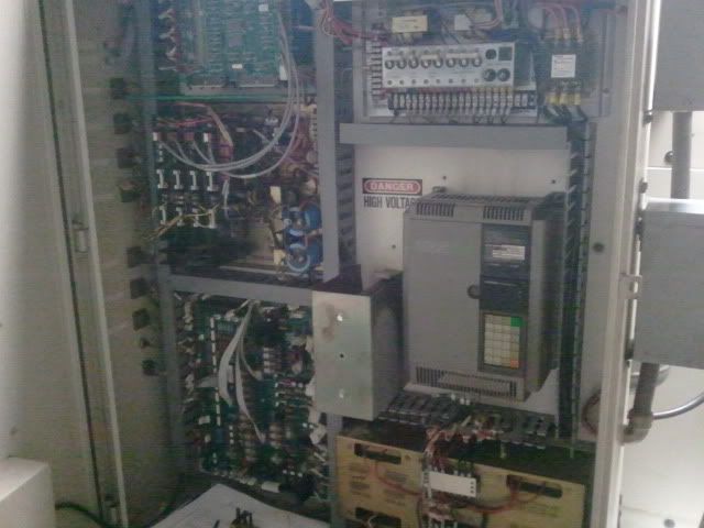
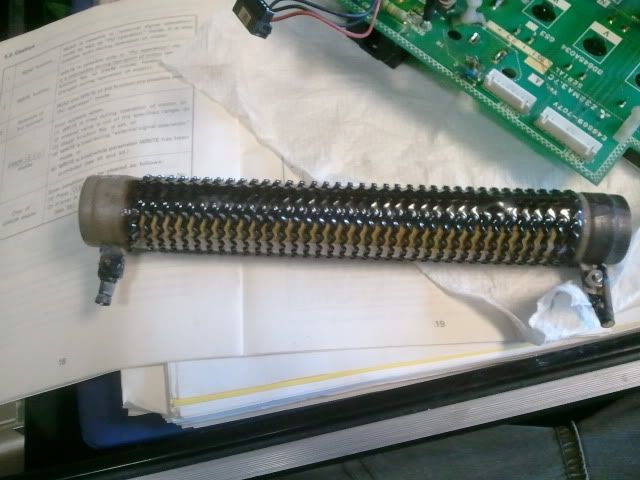
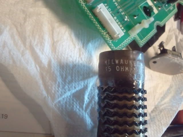
Well I am almost done with the rebuild on my VF-1. I went out to the shop today with the intentions of loading the program, setting up the stock and giving it a dry run. After powering it up, homing it and a few movements I noticed the characteristic electrical burning smell. I quickly shut it down and open the rear door only to have smoke come billowing out at me!  After the smoke clears I get a chance to see what happened. Apparently the two spindle brake resistors got red hot and started to burn everything near to themselves. The servo resistor in between the two did not get hot. I let it cool off and powered it up again. The resistors immediately start to heat up. I shut it down again. I noticed that the drive had an error code E6E on the display, "Brake transistor fault detection." As far as I can tell, only the resistors are ruined and some wiring, so far. The wire looms are shot in a few places but they will serve their purpose "as is" for now. I Googled the drive and problem but came up with nothing.
Here is the information that I have gathered so far to try and diagnose what happened. The only work I have recently done to the mill was I put a rectifier bridge in to convert to AC voltage for the light to DC to run my new LED lights. If I unplug the LED and the rectifier the resistors still get hot at start up so I don't think that caused it, I hope. After I powered it up I homed it, moved it back to center of its travels, then homed it again. The auto power up is slow to home but the second time I homed it was at rapids. I think this may have been the point that something failed but I don't know. Also I got no over-temp alarms even thought the temp sensors got so hot they melted! The drive lists an input of 230v at 60 hz on the front panel. I am getting 244, 243, 242 from my phase converter while loaded. I am dead on 60 Hz as well. The drive is a Mitsubishi Freqrol-Z300 model# FR-Z320-3.7K.
I am so close to making parts that this makes me sick to my stomach!
Anyone out there have any advise?
Steve
PS. I am so ticked about this I have managed to consume 3 beers while writing this, benefits of a home shop and being able to call it a day whenever.
After the smoke clears I get a chance to see what happened. Apparently the two spindle brake resistors got red hot and started to burn everything near to themselves. The servo resistor in between the two did not get hot. I let it cool off and powered it up again. The resistors immediately start to heat up. I shut it down again. I noticed that the drive had an error code E6E on the display, "Brake transistor fault detection." As far as I can tell, only the resistors are ruined and some wiring, so far. The wire looms are shot in a few places but they will serve their purpose "as is" for now. I Googled the drive and problem but came up with nothing. Here is the information that I have gathered so far to try and diagnose what happened. The only work I have recently done to the mill was I put a rectifier bridge in to convert to AC voltage for the light to DC to run my new LED lights. If I unplug the LED and the rectifier the resistors still get hot at start up so I don't think that caused it, I hope. After I powered it up I homed it, moved it back to center of its travels, then homed it again. The auto power up is slow to home but the second time I homed it was at rapids. I think this may have been the point that something failed but I don't know. Also I got no over-temp alarms even thought the temp sensors got so hot they melted! The drive lists an input of 230v at 60 hz on the front panel. I am getting 244, 243, 242 from my phase converter while loaded. I am dead on 60 Hz as well. The drive is a Mitsubishi Freqrol-Z300 model# FR-Z320-3.7K.
I am so close to making parts that this makes me sick to my stomach!
Anyone out there have any advise?
Steve
PS. I am so ticked about this I have managed to consume 3 beers while writing this, benefits of a home shop and being able to call it a day whenever.
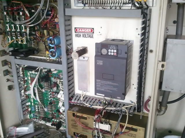
 The first thing I did was to make sure that the motor leads were the correct resistance against themselves and test for short to ground. Everything checked out good so I decided to open up the drive.


 I'll post what I find after I get a chance to get into it.

 I ran it yesterday for an hour or so trying to program it and I did not have any problems with the resistors getting hot. I thought everything was OK until about 10 minutes ago. I went out to change a few lines of code and realized that a lot of the code was not sent properly from my laptop so I shut it down. Just to check I opened the cabinet and sure enough the resistors were glowing red. At least I caught it this time before anything was damaged like last time. I know that the transistor is probably to blame again but what could cause it to fail? I am wondering if it is something outside the spindle drive that is causing it.