What's new
What's new

Emergency Stop Question 1997 Bridgeport Romi S lathe

Chevy427z

Stainless
Joined
Oct 12, 2004
Location
Clinton, North Carolina
Hi folks.

Out of the blue, upon power up, I am getting an error message "Emergency Stop has been Activated" and nothing will move. I have twisted both E-Stop buttons so they are in "operational" position. Coincidentally, occasionally I will get a "low air pressure" indication as well. Which makes no sense to me as there is nothing pneumatically controlled on the machine except for a collet closer which hasn't been installed for years.

Any thoughts where to get started? Electronics is not a strong suit for me. Many thanks!

Mark
 
The "low air pressure" will shut the machine down. The logic says that if the pressure is low, a part might come out.
There are other interlocks on the machine. This question is best answered on the CNC forum.
JR
 
Thank you JR! I'll try posting over there. I understand how pneumatics work. That's the odd thing, as mentioned, there is nothing pneumatically controlled on this lathe, aside from an aftermarket collet closer that hasn't been hooked up for years. No on board pneumatic switches that I am aware of.
 
You can get the E stop error when the Path is low on air or oil, so I would definitely check both. Can also get the E stop error when the AUF board isnt getting 24VDC.

Jon
H&W Machine Repair
 
You can get the E stop error when the Path is low on air or oil, so I would definitely check both. Can also get the E stop error when the AUF board isnt getting 24VDC.
Jon
H&W Machine Repair

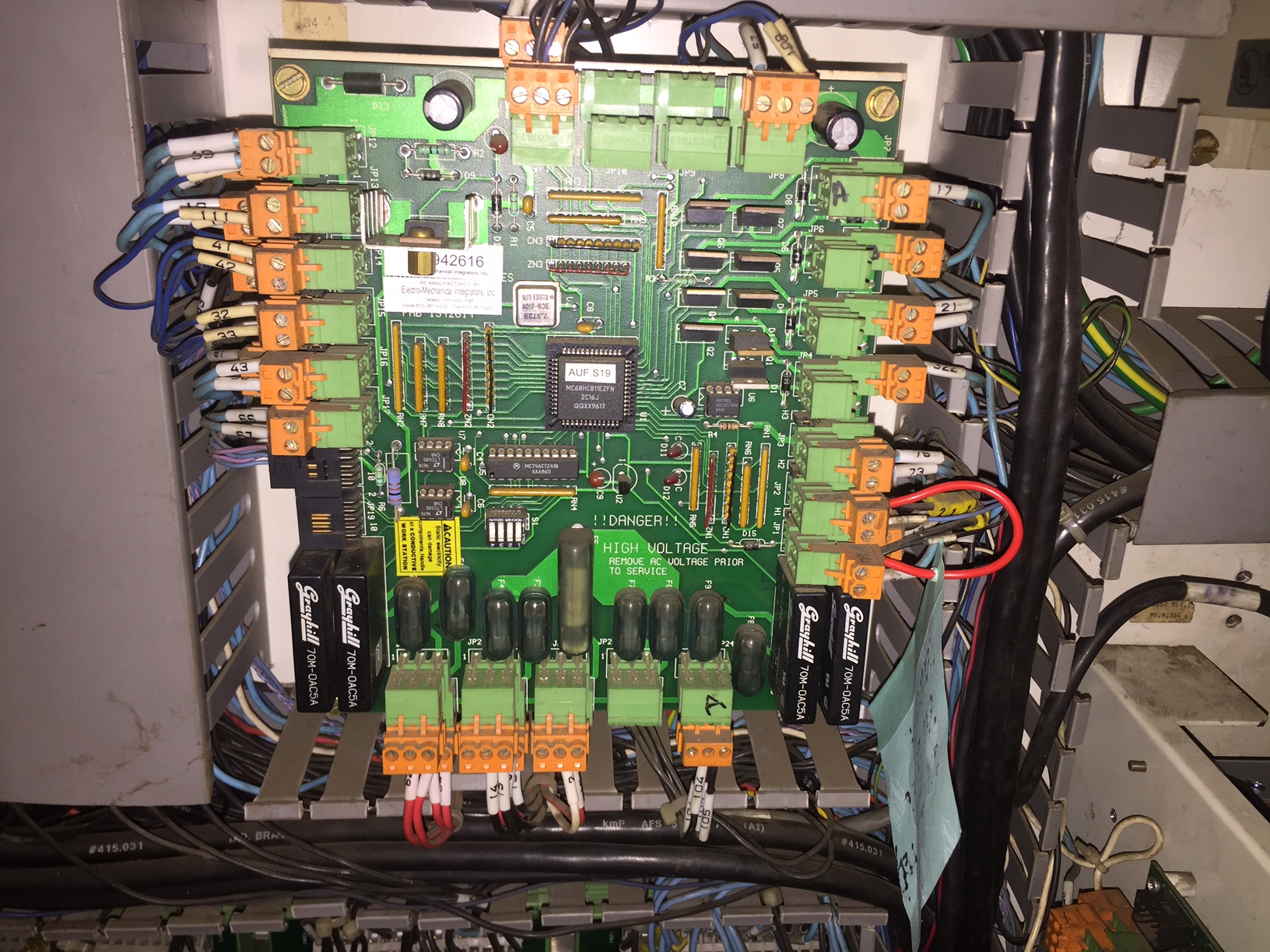
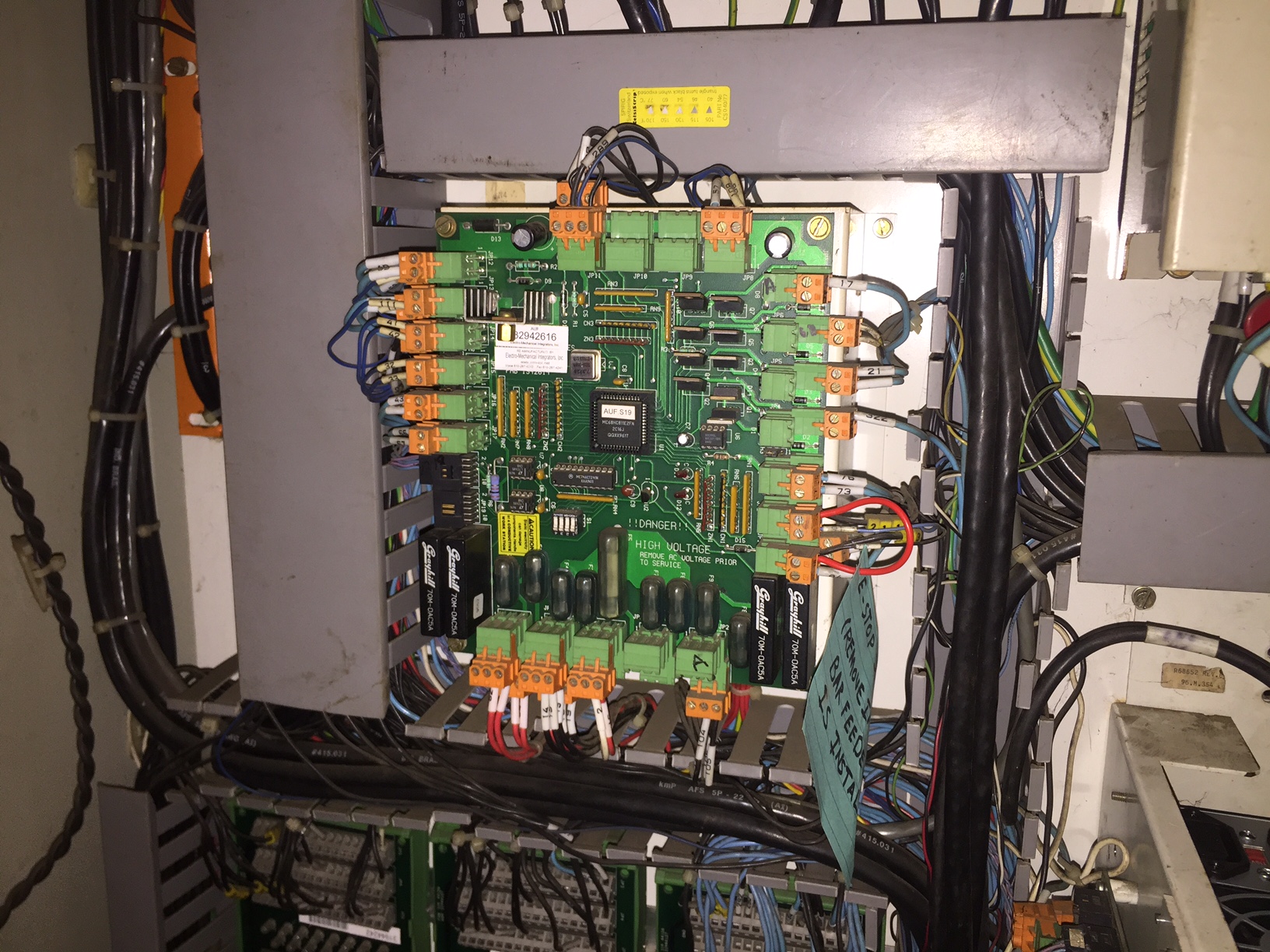
Jon has the most likely answer. I go through this from time to time because I have not gotten around to cleaning the pins for oxidation and putting a slight kink in them to insure contact in the cheesy plugs they used. Upper left corner of the AUF board. JP12 1A and 2A are the 24V. Most likely you will not see any lights ( LEDs ) illuminated on your AUF. Pull the connector off, replace it, and you should see it power up.
 
Just to put some more knowledge out, cause I ran into this 2 weeks ago.. JP12 AND JP13 are both 24VDC. I was under the assumption that it was only 12, but both 12 and 13 are 24VDC. Both of my JP12 connectors werent allowing 24VDC through, and an old friend who was a BP engineer told me 13 was as well.

Hope that helps someone in the future.

Jon
H&W Machine Repair
 
Jon,

This is true, but it is JP12 that supplies the AUF. JP13 is the output of 24V for the use of inputting to the GPAUF board. ( lower left corner connection ) This is also verified on the electrical schematic. Still a good idea to verify their connections, though. I actually really like these turning centers. They are built like brick shite houses, and then some. They hold sizes nicely, and for the most part - just run.

The weak link in it all seems to be the electrical connections. Why Bridgeport ever chose the ones they did will baffle me forever. Aside from blowing a board from old age and some mild corrosion messing with the pump motor, they are the single cause of every other issue I have encountered.

Otherwise, it's been a damn good turning center. Likely more attributable to Romi than Bridgeport... :cool:
 
Hi folks.

I am having a hard time finding what you all are talking about. I've found a board marked GPAUF-R but it's mounted perpendicular to another board that has those cheesy connections on it. I'm not seeing any JP12. I am not seeing any "connection" to remove and replace, but I am finding two sets of A1 and A2 that I removed and replaced. They look to be in fine condition.

I don't see any air connections but I did check the oil level which was half full. Filled it up, no change.

And you are correct, no LEDs lit up on what I think is the AUF board.

I checked both E-Stop buttons, both functioning as they should.

I await further instructions :-)

Mark

Edited: I agree about the quality of this machine. That's why I bought it. I got it for a song as it had "issues", the biggest so far being the X-axis servo drive. That's another story, a good one, and that's all fixed. It has an intermittent homing issue, but that'll be the subject of another post, I'm able to work around that for the time being.
 

Attachments

  • board 1.jpg
    board 1.jpg
    100 KB · Views: 257
  • board 2.jpg
    board 2.jpg
    96 KB · Views: 254
Last edited:
Pic of AUF board.

AUF-BOARD-1.JPG


AUF-BOARD-3.JPG
 
Hmmmm

I haven't seen anything like this yet. What year is this machine? Mine is a 1997. Are they similar? Where would I find this board positioned in the cabinet? Thank you for posting!

Mark
 
Hmmmm

I haven't seen anything like this yet. What year is this machine? Mine is a 1997. Are they similar? Where would I find this board positioned in the cabinet? Thank you for posting!

Mark


Ahhhhh... sounds like you may have an EZ-Path. I thought your original title was a typo error. My mistake. You should still have an AUF boar though, I believe. It's just in a different location. Ours is a PowerPath. ( affectionately known as a Bridgeport PsychoPath Turning Center to many )
 
Yes, my apologies. It is an EZ-Path. I forgot that in the original post title. I'll dig a little deeper, but I think I've uncovered all of the major boards, hence my pictures above. I thank you for time and efforts!

Mark
 
According to your picture, JP12 is in the upper left hand corner, just next to a diode. That is your 24VDC signal. If you are getting 24VDC at the pin yet the lights arent turning on on the board, then something in the board is killing your 24VDC.

Jon
H&W Machine Repair
 
Thank you very much for the additional information Jon. I was hoping you might be able to relate a little more to my particular machine.

I have a friend who's better equipped in the realm of electronics helping me now. Looks like 24v is not getting to this board. Tracking it down, step by step. He's got my schematics to study and will attack again at a later date. Will follow up then.

Thanks again for your time!

Mark
 
@Mark have you checked your 5/12VDC coming off of your power supply?

Red to black is 5VDC
Yellow to black is 12VDC

The tolerances for those voltages are quite small, so you are looking for about 5.0 to 5.15 (5.2 maybe, but that can make the machine finicky) and 12 is a little larger of a tolerance, i would go maybe 12 ti 12.4.

Jon
H&W Machine Repair
 
According to your picture, JP12 is in the upper left hand corner, just next to a diode. That is your 24VDC signal. If you are getting 24VDC at the pin yet the lights arent turning on on the board, then something in the board is killing your 24VDC.

Jon
H&W Machine Repair

I am confused... Are you sure you are not looking at the picture that I posted, Jon? Mark's picture shows a GPAUF board from what I can see. Maybe I am missing something, but thought to ask.
 
Thank you for asking Zahnrad!

You're not the only only one confused! LOL

Jon, I'll give my buddy the additional info. We work together, but live about an hour apart. This machine is in my home shop/garage.

Thanks again gents!

Mark
 
@Zahnrad I totally was looking at yours lol

I typically look at PM before I have had my pot of BRCC, so alot of the time i am a little slow. Totally my bad.

Jon
H&W Machine Repair


Back
Top