What's new
What's new

Hardinge BB4 Horizontal Mill Motor Controls and Wiring Questions

FrankW

Plastic
Joined
Mar 18, 2007
Location
Johns Island
Hello,

I have a BB4 mill as shown in this thread:

http://www.practicalmachinist.com/vb/bridgeport-hardinge-mills-lathes/identify-hardinge-mill-186444/

The previous owner replaced the original electric motor with a single phase 3/4 HP 1725 motor and removed the original forward/reverse control lever and high/low speed control lever.

The original motor pulley was damaged and replaced by an off-the-shelf aluminum pulley. This configuration did not allow for changing speeds as the belt lengths were not consistent across the pulley sheaves.

I have repaired the broken flange on the original motor pulley and intend to reinstall the original pulley on the motor.

My questions:

Does anyone have pictures of the original motor location with the pulley installed?

Did the BB4 have a two speed motor or a single speed motor? What were the motor speeds?

Does anyone have pictures of the control linkages that will help me recreate the original forward/reverse lever and the high/low speed lever (if this was available)?

I have several other machines with VFD controls for 3 phase motors, but would like to see the original configuration before I decide how to proceed with the motor and controls for the BB4.

Thanks for the help,

Frank
 
Frank, we have been waiting since August 2009 for you to show pictures of the side and back of your mill. I want to see how the power feed gearing was attached to the base and other details. As I said then, I have the same mill, but have never seen one with power feed installed. I do have power feed for the old Cataract flat belt pulley bench mills.

The bench mills used the same motor as the lathes of that period. It is a big heavy two-speed made by Louis Allis or Diehl with an obsolete frame size, including a 3/4" shaft. The high speed is 1750 RPM with 3/4 HP and the low speed is 875 RPM with 3/8 HP.

If the motor mount and controls are gone, I would put in a single speed 1750 RPM 1 HP 3 PH and 110 V VFD. The four step pulley would still be a good thing. The catalog says the mill ran 180 to 3000 RPM, but slower than 180 might prove useful for large HSS saws in alloy steel.

My mill is gridlocked between other machines, so I can't get to it very well. I did take a few pictures as best I could.

Larry
 
As luck would have it, I have a BB4 i am selling, i have pictures of the linkage i can post for you tonight (when i get home, images are still on the camera there).

toag
 
So i am a day late and a dollar short... I collapsed on the coach while the wife watched some vampire show.
here are some images for you.
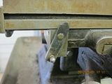
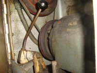
Image one is a picture of the linkage, the one on the right is home made (3/8" square stock, 10-32 threaded hole for the linkage rod)
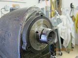
Image 2 is the an internal picture of the linkage looking up, the three belts (which need replaced... ) are at the bottom of the picture
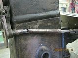
IMage 3 is a view of the linkage from the rear looking in. the one on the left (brake/on iirc) is supposed to be net like that to make the linkage work.
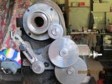
image 4 is simlar to image 3 showing how the linkage hooks to the levers.

let me know if this helps or if you need more info.
 

Attachments

  • linkage_1.jpg
    linkage_1.jpg
    86.8 KB · Views: 518
  • Linkage_2.jpg
    Linkage_2.jpg
    88 KB · Views: 546
  • linkage_3.jpg
    linkage_3.jpg
    83 KB · Views: 476
  • linkage_4.jpg
    linkage_4.jpg
    86.1 KB · Views: 415
More Pictures

Thanks very much for the great pictures of the linkages!

Here are a few more pictures of my BB4:


Thanks again for all the great information,

Frank
 
np,

yours ismuch like the one i have here, do you have start and stop contacts for the x power feed? I can make some drawings if you need.
 
The picture of the back of the mill shows what seems to be a spare gear located bottom left. This gear does not appear to have any other function other than to replace the gear that meshes with the spindle gear. I assume changing this gear will change the power feed speeds.

Thanks to Larry for the pictures of the pulley and motor setup. This is the view I need to properly position the motor and repaired pulley.

Frank
 
More pictures. As you can see, my spindle nose is correct for the BB4 mill. It is plain cylindrical and cannot mount a lathe chuck. My mill came with a period jointed arm machine lamp mounted to the headstock boss that would carry the lever collet closer on the lathe version. See the last picture in post number 8. Mine has the tapped hole in the rear of the base where a power feed bracket could be mounted. Note the hole is off-center with respect to the T-slot.

I think Frank's mill has a lathe headstock on it. The 1936 model headstocks for lathes have a threaded plug on top that contains a spring for the spindle brake. The serial number plate is an access cover that allows one to adjust the brake action. The mill headstock has a boss with no threaded hole on top, so there is no spindle brake.

The gears are identical to the ones for the Cataract lathe screwcutting attachment. I have made a few of them to fill out my set for the lathe attachment. But I am currently making missing parts for a second screwcutting attachment, and will need to make a full set of gears for it.

Larry

DSC01300.jpgDSC01299.jpgDSC01301.jpgDSC01295.jpg
 
More pictures. Descriptions of the bench mills from the 1946 brochure. Back of my 1936 BB2V showing the tapped hole for the power feed bracket is on-center with regard to the T-slot. The vertical head has no way to attach the driving gear for power feed. On my mill, that hole was used to attach a block to hold the set of 2VB collets. The serial number for the 2VB is on one of the upper round belt access covers.

Larry

Hardinge BB4 bench mill descr 1946 brochure.jpgHardinge BB2V bench mill descr 1946 brochure.jpgDSC01297.jpgDSC01298.jpg
 
The picture of the back of the mill shows what seems to be a spare gear located bottom left. This gear does not appear to have any other function other than to replace the gear that meshes with the spindle gear. I assume changing this gear will change the power feed speeds.

Thanks to Larry for the pictures of the pulley and motor setup. This is the view I need to properly position the motor and repaired pulley.

Frank

I believe the gear on the rear arm is for reversing the direction of feed. My mill power feed unit is missing some parts which I will have to make, including some gears. I don't expect to actually ever use it, but I like to fix stuff.

If you look at Tony's page on Cataract mills, there is a picture of this type of power feed unit, including a stack of change gears. I count a total of 16 gears in the picture. The Cataract catalog 15 says that the bench mills use the lathe screw cutting attachment for power feed. I don't know when Hardinge designed this power feed unit that only works on the mills.

Power feed is about 2/3 down on this page: Page Title


Larry


Back
Top