What's new
What's new

Hardinge TM-UM mill with a DC motor wiring issuesI just picked up a Hardinge

hayseed

Plastic
Joined
Aug 5, 2010
Location
Tucson, AZ
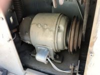
I just picked up a Hardinge TM-UM mill that I was told had a three phase motor, but after I got it I found out it has a 230V DC motor. I'm fairly good with electric motors but the only DC motors I've dealt with were automotive related.

On investigation just what this motor is I found it has 3 sets of windings. Armature, series, and shunt. when I got this there was a variable autotransformer( better known as a Variac ) and two small full wave bridge rectifiers hooked up with some really sketchy wiring, down right scary wiring!

On the motor who ever did this fine job of wiring only wired in the shunt windings and the armature, the series windings were just left unhooked and taped. the motor does run like it is and the variable speed function does work. BUT, this motor is probably somewhat older than the mill itself which was made in 1955. I want this motor to last another 60+ years, so wiring it properly is my desire. As I understand it there are a few different ways it can be wired. what Im thinking I want to do is wire it as a long shunt compound motor. I want to retain the variable speed function and have the motor reversible. I'm cornfusing myself when trying to figure out the wiring for the reversing function.

Is there anyone more familiar than myself with these type of motor who is willing to help straighten out my muddled brain?:ack2::ack2:

John from Tucson, AZ.

Armature, (shunt wound), Field, and a Series winding for load compensating I think you meant.

I have a couple of DC motors in that winding class, yes. Common on 10EE, WiaD and Modular era, not MG-era.

When using Solid State DC Drives, we often abandon compounding or compensating windings (two different ways of chasing similar goals). The Drives have enough control to not need their help.

Your winding was probably abandoned because it needs special treatment when doing Armature reversing. Not hard. Coupla more diodes can do that for you.

There's a thread on PM some years back that concisely goes into the whyso and wherefor and how to "upright" those as need polarity correction when reversing so the compensation still corrects, rather than fights and worsens.

I'll try to find that link for you to read.

Meanwhile - more info on the motor if you have any.

230 VDC motors are a tad problematic in the the US single-phase environment. They expected 3-Phase upstream before rectification. Our 220-240 VAC mains is not enough to operate them properly on but one phase without a boost transformer as it only nets to 180-190 VDC after rectification and "integration" done by the motor itself.

Your Variac addresses that, but with neither the winding intended to help the motor regulate its own self being connected, nor a DC Drive with dynamic load regulation, there'll be good deal of drop in RPM under load, and it won't be very stable of predictable unless the motor is seriously oversized for the load - much as if would have to be if converted to VFD.

Other than the 10EE motors here (several) all my DC motors (more yet) are 180 VDC wound.
That lets me use inexpensive KB-Penta DC Drives and need no boost transformer.

The 10EE ones need boost transformer and the costlier Eurotherm/Parker DC Drive that can operate at the higher voltage.

Should YOU switch to a 180 VDC motor // ELSE Parker SSD DC drive for the very significant improvement?

Not enough information yet.

That mill - as with my Burke #4 - needs only about 1 HP if it still has its OEM set of mechanical ratio choices.

If not, 2 to 3 HP "nominal", as HP and torque have to work over a broad range to make up for lack of belt or gear changes and that affects motor efficiency.

Helpful if we can see the motor nameplate. AND your driveline and its ratios so as to put better sight of your options on the table.

Bill
 
Now if I can get the photo of the data plate to upload. I am on a very limited budget to get the mill up and running so new motors are out of the question.

All of the belts and pulleys and drive is factory equipment. The DC motor is 1 HP, 230 V 1150 RPM GE motor39D1EC61-494D-457E-8AAE-DD11C1C7AE89.jpg217836AD-BCBD-4A0A-9050-E87DB683DAE2.jpg654F24F3-6C92-45FE-A603-378765F1ABB4.jpg
 
Sorry the picture isn’t the best! Here is all the data:

Motor GE
M# 5b204a56
S#7203168-pm
Type b
Frame 204
HP 1
Rpm 1150
Volts 230
Amp 4.24
Winding Stab. Sh.
Duty D.P.P. Cont. 50C
Direct Current motor
 
Got it. I have some research to do.

Fear not - you should be able to make chips more easily than the PO did, and without much extra spend.

Meanwhile.. cleaning, cleaning, cleaning, and with care not to use materials nor methods as may do more harm than good, especially to electricals, bearings, and the crevices of sliding fits and gibs.

I like to start with chip brushes and tub of "Goop" waterless, non-abrasive hand cleaner of all things!

And.. can you get any information for us off that old Variac?

PS: Even "zoomed" that nameplate is sparse on info. Do you even HAVE "Field" leads?"

I'm not expecting a permanent magnet field here on that Kinamatic-family housing shape. 100 VDC or 200 VDC field at a bit under one Amp, rather.
 
...PS: Even "zoomed" that nameplate is sparse on info. Do you even HAVE "Field" leads?" ...

He posted this on another forum, "I was wrong on the labels for the leads they are A1, A2, F1, F2, S1,and one unmarked."

So, A for armature, F for field, and S for series (compensating). I suppose the frame is grounded.

Larry
 
He posted this on another forum, "I was wrong on the labels for the leads they are A1, A2, F1, F2, S1,and one unmarked."

So, A for armature, F for field, and S for series (compensating). I suppose the frame is grounded.

Larry

Thanks for that! The other one will be "S2", then.

Going by a very similar 3 HP small-frame Reliance I have here that has a supplemental plate showing those connections, S1 & S2 are meant to be placed in SERIES with the Armature, which end and which polarity determined by choice of the direction of rotation such that they add to stability rather than fighting it.

"Mechanically" switching these as the motor is reversed requires extra "stuff" - eg: supplemental contacts, more complex contactors, synced relays.

4Q DC Drives don't HAVE ANY gross-motion switchgear, so a diode bridge can be used to "correct" the S1, S2 polarity automagically. Or we can ignore it, as the DC Drive has far better load regulation, anyway.

IF .. the "raw" Variac & rectifier is to be all there is, here, it would be easiest and cheapest to re-connect S1, S2 to favour "majority" direction of rotation only, to get at least "some" load regulation.

Currents involved are low enough that it wouldn't be costly to incorporate their reversing into a reversing switch/contactor/relay array synced to Armature reversing. Just on the messy side, mare's nest of wiring and such.

I'd be inclined to leave them disconnected for now.

Once cleaned-up and put into service, the OP's actual milling loads just might be light enough that in-motor supplemental coil regulation isn't really an issue. Shunt-wound DC motors are pretty good at self-stabilizing, even "naked".

These are far, far more nicely made mills than a Burke #4, but also lighter in max workloads. The rougher-built Burke has a B&S #9 spindle and "just" enough frame & knee strength to actually use it at up to 3 HP, historically, and 2 HP rather more often.

The Hardinge is more likely to loose grip on its tools before it hits the same HP wall.

That is not, actually, a "bad thing", given how little meat there is in the knee & such of either mill. A nineteen-teens/twenties Rockford of about the same overall size might easily eat the lunch of either of them.
 
In case some readers are not familiar with the Hardinge TM and UM mills, here are some notes.

The OEM motor was 3/4 HP at 1725 RPM and 3/8 HP at 975 RPM, with spindle speeds of 110, 220, 400, 600, 800, 925, 1200, and 1850 RPM.

The OEM 5C shank cutter arbors have oversized keyways in the shank to prevent shearing the indexing key in the spindle. The end of the spindle flange has two large slots to drive a pair of axial keys on the arbor collar. The arbors were made in 7/8 and 1 inch diameter and do not have keyways to engage the keyways found in the bores of most cutters.

So big cutters that run with the motor in the lowest speed of 110 only get 3/8 HP. The 220 speed will have 3/4 HP.

Larry

You could have honestly added that they can do downright lovely work - so long as appropriately tooled and operated within these modest - but nonetheless very useful - bounds. Hardinge never pretended to be K&T. Both firms were good as can be. In their own chosen space.

:)

He'll probably have 1/2 to 1 HP - RPM dependent - and more "reserve" torque, nearly always - from that Dee Cee motor.

That said, it will not be all that smooth off raw single-phase.

10EE's - even with very good single-phase solid-state DC Drives, still need a largish ripple-filter (20 milli-Henry @ 20A or so) to even stay close to the smoothness of their rotating-power MG ancestors.
 
Got it. I have some research to do.

Fear not - you should be able to make chips more easily than the PO did, and without much extra spend.

Meanwhile.. cleaning, cleaning, cleaning, and with care not to use materials nor methods as may do more harm than good, especially to electricals, bearings, and the crevices of sliding fits and gibs.

I like to start with chip brushes and tub of "Goop" waterless, non-abrasive hand cleaner of all things!

And.. can you get any information for us off that old Variac?

PS: Even "zoomed" that nameplate is sparse on info. Do you even HAVE "Field" leads?"

I'm not expecting a permanent magnet field here on that Kinamatic-family housing shape. 100 VDC or 200 VDC field at a bit under one Amp, rather.

Here’s a photo of the data plate on the variac.
The second photo shows how the wiring was when I got the mill.
I’m wondering why the photos come out fuzzy when I upload them to this sight, they are nice and clear on my iPad .


857C8B7B-29BC-4DC8-8762-DA9653D6CE88.jpgD6C20C03-5870-4E79-A866-6AF5BCCA906F.jpg


Back
Top