What's new
What's new

Problem Locking Hardinge Compound on DV59

ChipChaff

Cast Iron
Joined
Dec 15, 2007
Location
Mid-Wisconsin
Hi all,

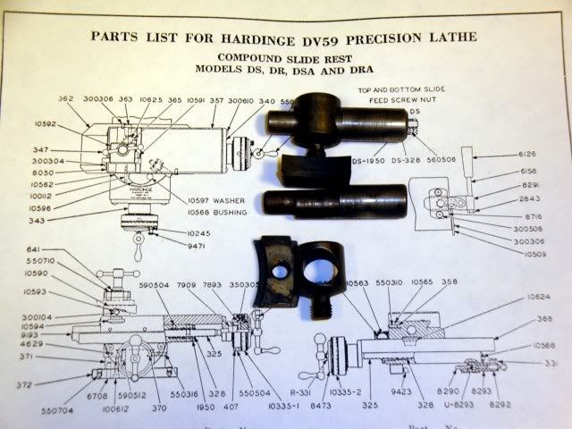
I just bought (stripped, repainted, and tooled - thanks to this site) a Hardinge DV59 with compound cross slide from a school via a machinery dealer - who was very fair. It works beautifully but I've had a problem in locking the compound to the cross slide.

Please forgive me if I don't use the correct terminology - I just barely passed Plastic - but there are two hex headed plugs with three eccentric planes each that lock the top compound slide to the bottom cross slide. The one on the left side of the compound crank locks in nice and tight and stands proud when it's snugged in. The one on the right (back) side rotates freely and the head of the plug sinks into the hole without binding at any point. It's not the plugs as I've swapped them and each locks in tightly on the left side hole and neither locks in on the right and there's no galling or wear apparent on either plug. Before I start tearing it apart, do you think the assembly is missing a part or is there some alignment trick I'm not seeing, or do you thing some ham handed student just wallowed out the locking surfaces in the hole? If this is a common problem, is there a common fix? I'd hate to have to find another one - I paid less for the lathe and tooling than I've seen compounds listed for on e(yech)Bay.
Thanks,
Chip
 
I seem to recall that the rear one snugs down on a fitting that is threaded together, and
that the level of 'snug' is adjustable by threading the fittings two parts together more
or less.

The lock shafts are not held in by anything other than the two button head screws,
if you remove the screws and jigger the lock screws out using an allen wrench, the
top will come off and you can inspect.

Jim
 
Thanks very much Jim.

I'll do as you suggest and see if I can figure out the adjustment for the back set-up. Nice to know it does adjust. I figured it was something I didn't understand vs metal damage as the unit, though tiny, seems to be built like the proverbial brick house.

As I play with the tooling and listen to the quiet whir of the head I'm becoming a complete Hardinge fan - great stuff.

Cheers,
Chip
 
Jim,

Wish it were otherwise, but it is broken. There are no adjustment screws that I could find. There are two vertical cylinders which are supposed to be affixed to a ring in the cross slide which have horizontal holes that, when the pins are inserted, join the cross slide with the compound. The pins with the eccentric cams fit in horizontal holes in the vertical pins and pull against the compound and the ring in the cross slide to lock the two together. One of the vertical cylinders has broken off of its mount on the cross slide, so turning the pin only raises and lowers the vertical cylinder rather than pulling the lower cross slide and the upper compound slide together. The good thing is that the one pin which does tighten the assembly seems to be enough to hold it in position. The down side is it looks like the broken cylinder would have to be welded or, at a minimum, silver soldered in place.

Any recommendations? Anyone ever sent one of these to Hardinge to fix?

Thanks,
Chip
 
Silver brazing is the quick fix, but it will draw the temper if the part was hardened. That is what I would try first. It is a simple part to make from O-1 if you have a lathe and mill. Sending stuff to Hardinge is asking for a huge bill, and even their parts prices are steep. I will look at my parts stock and see if I can spare one.

Larry
 
Larry,

Thanks for the input - and doubly for all the tooling.

I understand the brazing recommendation and drawback but 'm not clear on what it is you suggest I might fabricate.

I wish I hadn't dropped technical writing, but here goes . . . The two vertical columns are supposed to be affixed at their bases to opposing sides of the top surface of a flat 3" black steel ring which is held through its center hole to the cross slide. When the cross slide and the compound slide are mated together it is this ring (in part) which allows the compound slide to pivot on top of the cross slide. One of the columns has been sheared off of the ring at its base, probably as a result of over-torquing the locking pin. Comparing the base of the column and where it had been attached, it looks like the weld snapped.

If I'm missing an opportunity to make something, please let me know - I do have a mill and a now a pair of lathes along with plenty of time and no little enthusiasm. I'm not a welder (yet) and considering the precise alignments needed, I don't think I want to start with that as my first project.

I'll look forward to hearing back about the possibility of a replacement part - which I am guessing would be the flat ring with the two vertical columns - if you have one that would be an amazing stroke of good luck.

Cheers,
Chip
 
Tonight I will dismantle mine and see where my memory was faulty.

As mentioned, possibly a brand new piece fabricated by you?

Jim
 
There is no welding of the swivel locking components in the original Hardinge DSA, DSB or DSC slide rest for the DV59 lathe. Perhaps you have some other kind of slide rest or perhaps there was a clumsy repair in the past. Here is a picture of the Hardinge parts list with the actual locking parts laid out. The part numbers are: 363 draw bolt, the 365 lock bolt nut and the 10625 lock bolt. The lock bolt and nut are threaded, so there is an adjustment of the cam action of the draw bolt. There are two of each part in the slide rest.

I do not have any extras of these items.

Larry

DSCSlideRestLocks.jpg
 
Jim, Larry,
I understand now, having seen Larry's picture of the parts diagram. I didn't go far enough in dismantling the cross slide. The place where it looked to me like a weld had broken is actually the top of the threaded portion of what I've been calling the "vertical column" stuck in the hole in the flat ring. Now I understand what piece Larry was recommending I make and what Jim was saying I could adjust. I don't know whether it's a clumsy repair or just stuck together. I should be able to make a close copy of the intact piece and drill out the broken stub.
Thanks to both of you - I'll give it a shot today.
Chip
 
Last edited:
There is no need to drill out the broken threaded end of the lock bolt. It is a loose fit in a through tapped hole in the nut. The lock bolt is the part I said could be silver brazed if broken. I did not test it, but I bet it is hardened.

Larry
 
Thanks - it works

Jim & Larry,

Thanks again for the information. Jim, I'm glad you saw Larry's post before breaking yours down.

I made a replacement part which seems to work well out of chromoly but, based on what Larry said about the originals being tool steel, it is probably softer than it should be. Since the one original set holds the top slide in place pretty well by itself, mine should last if I treat it carefully. Still, I did call Hardinge to see what just the one piece would cost - $28 - so I went ahead and ordered one in case my piece doesn't hold up.

In any event, it was fun making the part - 28 TPI - and having it work the first time! - pretty exciting by mid-Wisconsin standards.:willy_nilly:

Thanks again for your help.
Chip
 
Hardinge heat-treats a lot of the small hardware like that. It's a nice touch.

Glad your part worked out OK, sometimes it's more fun to make 'em yourself as
you say. I spent three years in Madision, is that anywhere near mid-WI?

Great town.

Jim
 
Hi Jim,

I'm about an hour and a half WNW of Madison going towards Minneapolis and surrounded by agricultural land and small towns. We've got a square, flat 40 acre farmette, two horses, 29 chickens, 2 ducks, and we'll be getting 2 miniature donkeys at the end of the month.

Bow season starts tomorrow and that IS exciting!

Cheers,
Chip
 
Resurrecting an old one here, but this picture came in very handy for disassembling my recently acquired compound, so thank you Larry.

What are the differences between the models listed in the picture (DS, DR, DSA, DRA) or DSC?
 
DS is the original 1960 slide rest designed for the DV59 lathes with dovetail beds. DR is the same slide rest with a base that fits any of the 9" swing split bed lathes, and the R refers to the TR lathe, the last underneath drive split bed model.

The third letter, A, B, or C, reflects minor design changes that makes some parts not work on earlier versions. I don't recall all the changes, but I can say the first 1960 slide rest design had straight gibs and, at some date, the gibs were made tapered, so that is one of the changes.

The DV59 lathes themselves had a major redesign in addition to the slide rest redesign in 1960. Hardinge did not change the swing or dovetail bed dimensions, so the new 1960 DS slide rests fit the first DV59 lathes introduced in 1946. Similarly, Hardinge continued their old policy of making improved design components like the slide rest available in a version to fit lathes built as long ago as 1904.

Larry


Back
Top