What's new
What's new

What is most likely quill feed slippage area BP clone?

partsproduction

Titanium
Joined
Aug 22, 2011
Location
Oregon coast
An Eisen varispeed head on YCI Supermax iron, the head maybe 5 year old, The power quill feed worked fine until suddenly I needed it and it didn't. It's not in the clutch area, I've checked it out pretty well, with the spindle off and the feed engaged the handle won't "strip" the clutch even with good hand pressure, and the handwheel at the front operates the feed fine.
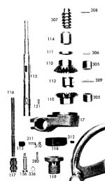
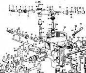
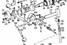
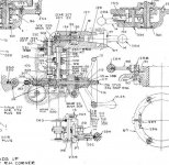
The problem seems to be a sheared key, either one of the two #10's, the #187, or #11 key, or perhaps the #59 pin? (http://kneemills.com/index.asp?html=Documentation)

Something is spinning on a shaft that's not supposed to be I think.
When I engage the feed it moves in all three gears but the slightest hand pressure opposing the feed stops it, without any clicking or other sounds. I bought an overhaul book and can live without the power quill feed for a while, but the question is this, which key in the drive train is the most likely to have sheared? Or, if the symptoms say it may be something else I'd love to hear it.
Thanks for any help in advance,
parts
 
When I got my Webb 4VH (Taiwan) Mill the up and down feed worked, but was intermittent. That is, it would got a bit, stop, and than start moving again. Like you, I checked the safety clutch and ruled that out.

Disassembly of the head immediately showed that one of the bevel gears in the worm gear cradle was missing two teeth. I changed both upper right-angle bevel gears and keys at the time and that fixed the problem. (#3 and #15)

I mention this only because I noticed that those keys are rather small and it seemed that they could easily have been part of the problem. In my case, neither of the two were sheared but it's possible that you have have one that is. If one of those keys is sheared, it would seem that could be your problem.

Apparently my mill had been owned by someone who used the down feed for drilling large holes. The manuals on Bridgeports and clones generally state that you should never drill holes larger then 3/8" when using the downfeed. In my case, after spending two days stripping and reassembling the head and shelling out $110 for the two gears and keys, I use the feed only for boring. LOL.

I suspect one of the bevel gear keys (#10 or 11).
 
Have yet to come across a sheared key. That's the job of the overload clutch. Properly set at the factory it should never need adjustment. To reset it make the adjustment while drilling. The adjustment will be correct if feed is applied to the drill at a constant rate.
Missing keys where they have dropped out during assembly, yes. Then there may be just enough pressure between the bore and a shaft to drive the feed until resistance overcomes the feed.

Some things to check;
The forward-neutral-reverse pin and the spring loaded ball that drops into each detent position on the pin. If the pin does not move far enough for the ball to hit the detent the symptoms may be similar. The three detent positions are visible on #116.
This part fits into #115.
By the way, does the quill feed up or does it slip under load?
Feed Engage 1.JPG
Remove the cover for the three position feed selector. Pick a feed and note the position of the back cover fork and where the sliding gears are positioned, take photos. Run the mill in any low speed with the worm in the head engaged for feed. A paint mixing stick held against the output gear will be enough friction to load the gear train in the head. This is a lot easier than pulling the top end off.

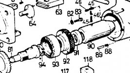
If the key is out for the worm gear #92, some friction but no drive.
BP4.JPG
#96, there is a group of parts responsible for setting the range of travel for this part. #45 release, #88 - 89 for engagement, and #118.
#118 is part of the feed trip group. Remove the scale and verify that #118 moves to the full extent of travel when the feed lever is engaged.
BP Feed 1.jpgBP Feed 3.JPGFeed 4~.JPG
John
 
Thanks to both of you for your responses. I first noticed this yesterday when using a 2 flute carbide end mill to make vertical plunge cuts in the sides of 6 303 split couplers. The split or saw cuts are opposite the key in a 2" OD X 3 1/4 303 part with 1" bore, the customer slips this onto the ends of two shafts and 5/16-24 socket cap bolts squeeze the split opening to hold things tightly together.
It was necessary to plunge without a pilot as the sides are on the edge of the 2" diameter bar, and so once the flat recesses are made then through holes are drilled through to the saw cut, then the tap drill and tapping.(Next time I do this job I'll plunge with a 5/16 end mill to take some pressure off the 1/2" EM, plus once the center is cut out I can follow with a 4 flute 1/2" EM which effectively lowers the chip load per tooth, and the feed will be under less strain.)

It's entirely possible the problem came into being on the first plunge cut, even at the lowest feed setting it only went about 70% of the needed depth and I had to finish by hand. So yes, I broke the "drill" size suggestion.

By the way, does the quill feed up or does it slip under load?
It works in all speeds and directions with constant motion, all feeds, with no indications of a problem until slight pressure is applied opposite the feed motion.
In fact it seems to be in perfect working order until a fingertip pushes back on the handle. :)
The forward reverse sleeve ball detent seems to be working normally, I watched the gears under that cover as it was running, and I tried to force them slightly with a lever while stopped to see if I could see anything slipping, but the problem appears to me to be earlier in the feed train, somewhere between the three gear cluster and the worm gear cradle above.
If the key is out for the worm gear #92, some friction but no drive.
I'm pretty sure that's not where it is because I can turn the outer handwheel shaft while applying opposing pressure on the feed handle and nothing slips that late in the train.
#96, there is a group of parts responsible for setting the range of travel for this part. #45 release, #88 - 89 for engagement, and #118.
Again, for the same reason, I think everything below the downward shaft from the upper area is working well, that might not include key #196 at the lower end of the shaft.
I think I'll hook a sling on the upper head, undo the three nuts that hold it on and hoist it off, is there anything that might cause an surprise if I do that? Once the upper housing is off I can carefully lever the gears while looking for what is slipping. I just cannot afford to have this mill "stuck" down for any length of time, it is probably the most diversely useful machine in the whole shop, though I do have a Shizouka Bandit controlled mill if necessary.
The fear is getting it apart and not having it running Monday morning even without the feed working, I mean, not be able to get it back as it is now at least. I'll see what Youtube shows about that.
Thanks
 
If at all possible, I would try to do any work on the head without removing it. That's a miserable job and to do it safely, you would want a helper.

I found that I could do any work necessary by simply tilting the head. It's actualy easier to look at the parts you are concerned with when it's horizontal.

Just my .02.

I was able to remove and replace the motor myself using the table as a workspace. Here is when I replaced the belts after fixing the bevel gears. You can easily access any other parts without removing the head.

Webb%20Motor%20Replacement_zpshiwyt5ww.jpg
 
Thanks Newman, I think I'll try to lift the upper head using the overhead crane today, perhaps I should lay the head sideways, support it with a sling from the crane as I pull it off sideways.
I definitely think I need to get to that worm drive area and work down from there.
The alternative is to remove the three bolts and pull very carefully straight up, letting the crane to most of the grunting, but I'm concerned that there may be surprises involved. When working on (What I consider to be) complex apparatus I do hate surprises.
 
Yes, the top end can be lifted up by removing the three nuts. The hard part is the balance point and safety.
Keep the quill in the up position and raise the head assembly high enough for blocking. Keep the splined
shaft engaged in the bore.
Two slings 1/2" and a 'choke hold.'
About the 2:00 minute mark may be helpful:Bridgeport Lower Head Adjustments - YouTube
As for the other dude-tube, No the quill does not have to be replaced because the end is burred!
Just dress it:)
 
No the quill does not have to be replaced because the end is burred!
Just dress it

I wondered about the fuss on that, and didn't understand how the spline terminus got expanded. He tried to explain but it wasn't obvious enough for me. :o
 
I wondered about the fuss on that, and didn't understand how the spline terminus got expanded. He tried to explain but it wasn't obvious enough for me. :o

The end of the splined shaft sustains damage when the drawbar / collets are drawn way too tight.
The BFH is used to break the taper loose. That's when the drawbar, spacer, washer, et al is pounded into the top of the splined shaft.
It's not from running the spindle with a loose drawbar.
 
I'm like a little kid afraid of a chihuahua.

So, after taking the three speed cover/shifter off and running it at low RPM, watching the bronze gear behind the drive clutch (Which is out) I see now that it has to be exactly opposite of what I've been saying. The three gears rotate even when I try to load them when the upper worm is engaged. The little forward/reverse spindle keeps turning but the bronze gear behind the clutch sometimes does until a light load is applied. You were right John, now I need to find out why it's not getting from the horz. for/rev shaft to the clutch bronze gear. I'll watch some more youtube and see how that's taken apart. It seems that the worm that turns the bronze wheel behind the torque adjusting clutch is disconnected somehow, most likely spinning on the shaft. That wheel turns or stops with very slight load changes.

Looks like maybe #308 in your Dwg, a pin,,,or sumptin like that.

Maybe key #30 in my Dwg. Or #56 in my Dwg, a roll pin.
 
I took the spring out of the collar at the front end of the horizontal feed shaft, the one that makes the ball act as a detent, and sure as heck the spring was collapsed. So I fitted a new spring and installed it, the feed appeared to be working. I was overjoyed, until I reached up and put opposing pressure against the handle again.

My reasoning was that if a handwheel stuck at the front would operate the feed up or down then there is nothing slipping, but that was faulty.

The handwheel only moves the feed apart from the power feed train.

I know that the power feed through the three speed box is solid, but not that the small bevel gear at the lower end of it's output shaft is not slipping, as the handwheel has nothing to do with that source of rotation.

Looking at post 15 here, a photo (http://www.practicalmachinist.com/v...athes/power-quill-feed-wont-disengage-269278/) it appears to me that the small bevel gear has to be slipping, because if the pin that slides the dog clutch collar back and forth was broken the feed from it would be intermittent, but the feed is smooth and continuous.
If the worm at the rear end of the shaft was spinning then the handwheel at the front would slip too, it doesn't. As stated earlier, handwheel rotation produces solid feed action.

I can't see the key used by the small bevel gear at the outfeed of the three speed box down to the rev/frwd gears in the drawing I found, but since it is separate from the shaft in the photo (post 15) it seems like it has to have one. Now, if there were a sheared key there would that also produce intermittent rotation? Wouldn't the keys sheared edged catch etc?

A final question for anyone following this; Do I have to take the return clock spring off the rack shaft and slide the shaft one way or the other to remove the horizontal shaft #57? If so I'll live without the feed until I get some help. If the rev/frwd shaft and the feed shaft it fits into, and the worm at the rear end can come forward out of the head it should only take a few minutes to verify my theory, and maybe a few minutes more to repair. (Wishful thinking :D)

This feed mechanism deserves an animation, and that would sure make it clearer.
Thanks,
parts
 
Yes the clock spring has to come out as well as the shaft.
You may need a face spanner. Count the number of revolutions the clock spring is turned until it is relaxed. Too tight at assembly means premature failure of the spring. It is not meant to be a return. More of a balancing mechanism. Generally I set the spring so the quill does not drop when a #14 Jacobs is used.
There is a key at the end of the shaft that engages the bronze worm wheel of the feed clutch group. Do not tap or hammer the shaft to get the key to engage. Use a very sticky grease to hold the keys in place, unless there is some crazy glue around.
Set screws, there may be two. One to hold and one to dog. Check the freedom of motion after dogging down. The second set screw might turn the first and then the bushing pinches the shaft.

Here is an assembly drawing. the three bevel gears are the reason the handwheel turns but not the worm wheel.
If this is like another repair I did expect to find a sheared roll pin in the worm. That gives just enough friction to turn the worm wheel until a load is applied.
Feed Assembly Drawing 2.jpgFeed Assembly Drawing 1 (Large).jpgAbarnsleys Photo.jpgBP3.JPG
Abarnsley's most excellent photo.
John
 
Last edited:
Thank you very much John, that opens my understanding up a lot.

After my last post I went out and messed with it again, and I absolutely have no idea whether it's the worm that's letting it spin or the miter gear.

I got a special non marring wrench on the hand wheel shaft and finally carefully turned it to verify it working using the hand wheel input (I threw the original hand wheel away long ago) and I was wrong, bypassing the power feed input does not make positive quill movement when pressure is applied, so it could be the worm at the end of the shaft.

The book will be here in a few days, but at least I know a bit more of what to expect.
I hope to report what I found after I get it apart so later problem solvers will have the record of at least one problem's cause, and how to repair it.
 
Looking over your last dwg's in post #13 it appears that the output shaft with the reversing bevel gear attached must be pulled out from the top before the horizontal shaft can be pulled out. I was hoping I wouldn't have to lift the upper housing off, but now it seems both the vertical shaft from the upper worm/ miter gear drive cradle needs to be pulled plus the output shaft also has to come out. The three speed box's output shaft can't be pulled until the input shaft's swinging cradle is out of the way.

I'm impressed with the depth of thought the original engineers put into this, and feel blessed to perhaps finally begin to understand what they designed.
Still, I wish I didn't have to do all this stuff, heh heh.
 
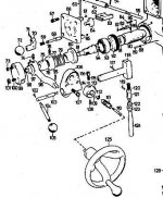
Yikes! It looks like the head needs to be removed from the ram adapter to access the setscrew that keeps the horizontal rack shaft in place, after taking the clock spring out I won't be able to slide the shaft to the left until I get the screws 250/350 out. (Bridgeport J-HEAD Diagram (PDF 1.03 MB)

Every time I look at it it's looking more like a whole weekend's work.
 
With the mill running use it to verify the fault. The path is from the engaged feed cradle down into the gears for the feed selection.
From there follow it down to the set of three bevel gears. At this point if the feed direction is selected forward or reverse this shaft that
the hand wheel is mounted on should be rotating. If it does not slip then the path down to the front bevel gear is good.
If as you say that the bronze worm gear slips then the shaft with the worm needs to be removed to inspect the roll pins for the worm, bevel, and the slotted spacer that is on the shaft between the two bevel gears.
A key task is to move the vertical shaft with the miter gear and the bushings up to clear the bevel gears.

Overall this is not an easy quick task and is more tedious and time consuming than most other Bridgeport repairs
The cradle is in the way and of course that set screw is at the back of the head:ack2:
John.
 
A sad verification, which is only because I'm so lazy. The slippage does seem to be somehwere between the miter gear attached at the bottom of the gear change box and the worm that drives the quill's rack shaft, because I can watch the worm turning until pressure is applied when it stops.

Meanwhile the speed change gears keep turning.

If the worm wheel on the quill rack shaft kept turning with pressure I'd know it was either the key there or at the pinion that drives the rack in the back of the quill, but that all stops moving, so it has to be where you said.

But the more I think about it the harder it is in my mind to fix! :D

My brother had a similar problem with his BP when he bought it, and he asked what I thought, and I was shocked to see all the parts laying on the garage floor, wasn't much help to him. I could see all of it and was mystified, he got it all back together though.

Thanks again for all your help, next weekend I should be ready to tear it down.
 
While we are on the subject of the feed...

Partsproduction does yours make a clicking sound as the manual quill feed handle is rotated?

I have a varispeed head that the feed works but it is also slipping... Another symptom is the manual quill feed handle makes a clicking sound as it is rotated.. Sort of like a spring loaded detent ball clicking as it is rotated...
 
Hi Swatkins, no, mine slips very smoothly, which is weird. Almost like a key fell out or it was assembled without one.
Is your problem the over torque clutch inside the rear round housing? That's adjustable if it is, though sometimes I understand that arm can bend and then it isn't closely forced into mesh with the other clutch half. #'s 80 and 93 in the first dwg. Let me know because I've run across a ton of info on how to set that if the spring is just adjusted too loosely. If the arm is bent I came upon answers to that too.


Back
Top