What's new
What's new

Bobcad/Bobcam engraving procedure

Mark A

Plastic
Joined
Jun 3, 2008
Location
Milwaukee, WI
Can anyone help me with an engraving issue with Bobcam/Bobcad in Solidworks?

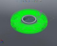
I am trying to engrave or cut some contoured grooves on a part that is shaped like a velocity stack and I can not get the cam software to create a toolpath.

Let me know what you need to know or if you need to see some pictures of what I have and what I am trying to do.

PS, other than Al's video's anyone have a good source of documentation (real world examples) to learn how to use Bobcam in Solidworks?

Thanks,

Mark
 
engraving bobcam video

Hello Mark,

I am sure I can help you with this. I ll even create a video for your application.

Question:

Is this 2D engraving or 3D engraving?

Do you have a sample file?

Al DePoalo
BobCAM Team Leader
 
Hi Al,

It is a 3D contour.

Let me know how to contact you and I can send you the file.

I already emailed the file last night and this morning and other problems to James over in tech support.

Thanks,

Mark
 
3D groove

Mark,

This groove that you are doing, are you programming a mill or lathe?
Also while I wait for the file are we running this grove up/ down the cone or around the id or od of the Stack?

Are you trying to program off a feature sketch body or edge?

Are you using a ball mill or some other cutter?

Al
 
groove cutting options

3D engrave

This would be based of an edge or sketch.

Center line tool path so it s not offsetting for the tool. Also it doesn t offer a roughing option so you would hve to use more than one feature to step it down.

Planner tool path

Based on feature or whole body

Set a boundary to keep the tool in the groove and set the tool path angle to match the groove. You can step down and the tool path is offset for the tool.

Pencil tool path

Based on whole body

Would work as long as the goove rad matches the tool rad and you don t need to rough.


I ll post more info once I have the file.

Al
 
Here is the top view of the part.

I am programming it for a mill.

I want to machine the groove. I already have the face machined using the Z rougher procedure.

I kept my same stock size and geometry, Created a procedure picking the engrave option and picked the loop of the groove.

I tried to run a tool path and nothing happens.

Extended length ball end mill, the grooves are on the inside of the part.

Can you get the part from James or can I email it to you directly?
 

Attachments

  • part A.jpg
    part A.jpg
    26.2 KB · Views: 472
Pencil would work on this file. What version of bobcam are you running?

I can get a copy of th file from james tomorrow when I am at the office.

Al
 
I am guessing you used a swept cut in order to put those grooves into the part.

If you were going to use the 3D engraving option use the sketch that you used to create the swept cut as the geometry selection for the 3D engrave.

I tired to use the pencil but I was wrong, it won't cut all the way down to the bottom.


Al
 

Attachments

  • pencil.jpg
    pencil.jpg
    17.2 KB · Views: 330
  • pencil_path.jpg
    pencil_path.jpg
    8.5 KB · Views: 279
  • 3D_engraving.jpg
    3D_engraving.jpg
    16.7 KB · Views: 355
  • 3D_engraving_geometry_selection.jpg
    3D_engraving_geometry_selection.jpg
    19.9 KB · Views: 326
  • 3D_engraving_path.jpg
    3D_engraving_path.jpg
    9.1 KB · Views: 276
Hi Al,

I used a spline curve and then did a extrude cut along the spline curve.

What I am looking for is a step by step procedure on how to use the engraving function. I did a search in the help files and I searched the internet and I could not find any information on how to actually use the engraving function.

Questions:

What do you pick as the stock size, stock geometry which creates the block of referenced material that the tool path cuts into.

What do you pick as a coordinate system and where would I place it. On the previous procedures I picked the top center of the part.

What do you pick for geometry, since there are multiple items do you pick each one?

How does the software work with custom tooling. I would be using an extended reach ball end mill.
 
BobCAM Options

Ok,

I have a copy of your file now. It looks like the "groove" you are tying to make may twist a little bit which creates a little bit of a undercut, or like a 5 axis move.

But I think what the idea is to have groves in the stack right?

Well after you have roughed the part out you can use a Z level finish to profile the walls and step down.

If you have the swept cut active the tool will follow the profile of the part and create the profile one level at a time stepping down in Z.

If you want just " Engrave" the groove you'll need to edit the drive curve for the swept to represent where you want the ball mill to go, on your file the curve wraps the "bell" so it might not be the best path for the ball mill to follow.

Think of 3D engrave as a manual tool path that will follow in XYZ like a 3D sketch.

Al
 
Questions:

What do you pick as the stock size, stock geometry which creates the block of referenced material that the tool path cuts into.


The stock size you use will

1) Affect your simulation to show you what you are cutting
2) Be used as a center line boundary for 3D tool paths
3) ADV rough uses the stock boundary as an open boundary, which means the tool will work from the outside in, where you would want the tool to start from the outside of the stock and work in.

So the stock size I would use in this example would be the stock size you are starting with.


What do you pick as a coordinate system and where would I place it. On the previous procedures I picked the top center of the part.

The coordinate system you use is your origin / work offset. So where ever you zero your stock on the machine needs to match the coordinate system setup used with BobCAM. Top center would work just fine.

What do you pick for geometry, since there are multiple items do you pick each one?

If you use ADV Rough and Z level finish you will pick the whole body and let the software do the rest.

If you are going to use 3D engrave for the groove you'll need to rotate and copy you 3D sketch to use as a center line tool path that the software will follow.


How does the software work with custom tooling. I would be using an extended reach ball end mill.

When you define you tool you can set the diameter, the corner rad, and the overall length and cutting length, so just define you tool appropriately. An extended reach ball end mill would not be considered custom tooling.
 
Face Cycle

1) The face cycle in BobCAM is base on a starting position. So when you select the geometry for the face cycle it only needs to be a point.

2) How does the software know what size to face to?

User input, the user defines the X and Y dimension of the face cycle.

This video goes through the steps of facing off this part.

Face - adepoalo's library

Al DePoalo
BobCAM Team Leader
 
Drill Tap Cycle

1) Our hole making cycles call more than one tool to create the type of hole cycle you selected. We can these tool patterns, and you can adjust and make changes to the tools that are called.

BobCAD-CAM V24 Getting Started 7 of 15 - YouTube

This video link shows how to make changes to the tool patterns. This video was done in V24, V2 works the same way.

2) Tap cycles are called from a pull down in the feature, If you want to add more taps or change the tools that are associated with the cycle you can.

How to add new taps

This link will bring you to BobCAD's knowledge base. There is a PDF you can download that explains how to add taps.

3) When we select our holes to tap we can pick from the feature tree, but tap cycles are called from a pull down.


Drill Tap - adepoalo's library

This video link shows how to tap the holes on this part.


Al DePoalo
BobCAM Team Leader
 
Pocket Cycle

1) The pocket cycle could be based on a sketch, face, edge or we could select the whole body and have the software find the pockets. In this case I am going to drill a pilot hole then come back and pocket, So I will use a point and the edges of the model to do this.

2) I want to drill a 1/2" Pilot hole what do I select to do this? I am using the a point that is on center, and will define the depth and hole size myself. If you want to drill holes sizes that are different that what is modeled in SolidWorks you can over ride them by user input.

3) Because the edges that I will be using are at the top of the part, I will need to define the pocket depth myself. BobCAM reads off the model so if the edge is at Z 0 that is where the program will pocket to, to over ride the just enter the depth that you want.

Depths are always positive numbers.

4) I made a choice to cut this pocket using 2D features, But I could have used a catch all ADV rough, you do need to make choices about how you are going to machine the part, and these steps are examples of what can be done. In no way am I saying you'll need to cut this part with the steps I am showing.

pocket - adepoalo's library

This video link shows the step for cutting this pocket.


Al DePoalo
BobCAM Team Leader
 
Advanced Rough

1) ADV Rough is a better 3 axis tool path for clearing stock on 3D models. It has lots of options for cutting and I am only covering a few of them.

2) Making changes to the model to support the machining cycle can and will be needed depending on how you are cutting the part. In this example I will create a surface to "block" the tool path from cutting in the center hole that I had previously pocketed out. I also measure the part to define the stopping point " bottom of job " where I don't want any tool path to be generated past.

ADV Tool Path - adepoalo's library

This video walks through these steps.

Al DePoalo
BobCAM Team Leader
 
Last edited:
Screen Shots Tool Paths

These are the screen shots of the tool paths. I will create a video of the simulation soon.

Al DePoalo
BobCAM Team Leader
 

Attachments

  • FACE.jpg
    FACE.jpg
    10.4 KB · Views: 256
  • Drill_2.jpg
    Drill_2.jpg
    7.4 KB · Views: 224
  • Pocket.jpg
    Pocket.jpg
    7.8 KB · Views: 179
  • ADV_R.jpg
    ADV_R.jpg
    9.9 KB · Views: 203
  • Radial_Finish.jpg
    Radial_Finish.jpg
    7.3 KB · Views: 225


Back
Top