Pattnmaker
Stainless
- Joined
- Nov 2, 2007
- Location
- Hamilton, Ontario
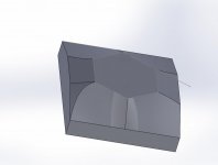
I am working on patterns for what look like simple parts. But there are large chamfers on the part that are cut to parallel planes vertically but there is an angle on how how much is chamfered on the top face. So the angle on the chamfer is a rolling bevel with angles different on each end of the chamfer and changing continuously from one end to the other. I was able to model that without too much trouble but there is then a chamfer off the side of the part intersecting with the first chamfer which also has to be a rolling bevel.
The drawing in both plan views and isometric show the line between the 2 chamfers as being straight but any way I model it I get curved lines where the 2 rolling bevels meet. I asked for a model and was sent a DWG not a 3d model so maybe there is no 3d model. Maybe I am just modeling it incorrectly but I am wondering if they could have drawn impossible geometry? Unfortunately my customer is the foundry not the final customer so communication is slow and through an intermediary.
The drawing in both plan views and isometric show the line between the 2 chamfers as being straight but any way I model it I get curved lines where the 2 rolling bevels meet. I asked for a model and was sent a DWG not a 3d model so maybe there is no 3d model. Maybe I am just modeling it incorrectly but I am wondering if they could have drawn impossible geometry? Unfortunately my customer is the foundry not the final customer so communication is slow and through an intermediary.