What's new
What's new

Complex Mold/Pattern Design of Non-Planar Parting Line - CAD Options and Workflow

goldenfab

Cast Iron
Joined
May 25, 2016
Location
USA Prescott , Arizona
Hi All,


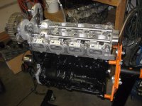
I am getting into fairly complexcasting and pattern work - currently working out the bugs of a 4 cylinder head for a car.

I have been using Alibre for all my CAD work. Its got me by mostly but I can't do non-planar parting lines, and it can't really do surface modeling. I used Blender and reverse engineered some patterns via mesh modeling but its too time consuming and mesh models are not the best for machining. Also creating non-planar parting lines was very labor intensive. I have played around with Fusion 360 using its T-Spline surfacing functions but its not very robust (partly because of user error).

I am looking for advice on a budget minded software/workflow where I can take a preliminary solids model and reverse engineer an existing solid model so as to get smoother free-flowing shapes. One specific example of a need as follows. When I design castings that have complex cores they are the result of leftover space after getting all the structural design modeled as a solid. The internal cavity (sand core) is the leftover space. But it is not good to have sharp edges like you get from prismatic solids modelers like Alibre and everything needs a draft angle about a parting line. Due to the complex shapes, solids modelers can not always compute draft and fillets, hence I am trying to solve the problem by re-designing the sand core with a surface modeler. A very important feature I must have is the ability to split molds/patterns that have a non-planar parting line, does not have to be automatic one button press solution but a software/workflow that does not take hours to do it would be sufficient. Here is a screen shot of the initial design of sand core shape.

original.jpg

This is a screenshot from blender of what I would want to redesign it as.

sculpted.jpg

Notice the non-planar parting line seen via the colors from draft analysis.

water_jacket_draft_color.jpg

I downloaded a demo of Rhino and the T-Splines plugin and am in the process of learning it. It seems a lot more robust than Fusion 360 as far as T-Splines are concerned when I draft less than ideal topology which I am working at improving. I would like to avoid spending the extra bucks on the T-Splines plugin if I can help it, I downloaded it to fix a surface I screwed up in Fusion. Anyways, my real question is do you think Rhino would be a good solution to the need I defined and what other software should I consider?


Thanks,
Adam
 
I cannot speak for Rhino, but back in my mold design days, I used a function in Solidworks to do non-planer parting lines. I think it was a little clunky (it might have been a new feature at the time) but I managed to do a fairly complex split with it. There were other tools that looked like they would make life easier, but that was about the time my mold customers bit the dust....
 
People designing cast shapes with that level of complexity, well... they usually get paid well enough to not be hunting around for free/cheap solutions to such problems. They tend to get paid pretty decently.
 
As gkoenig said, the level of cad you are using justifies the cost of a more capable cad system.

If you are only doing the design with no need for the 'cam' side of the software it is not horribly expensive (just somewhat!)
 
As gkoenig said, the level of cad you are using justifies the cost of a more capable cad system.

If you are only doing the design with no need for the 'cam' side of the software it is not horribly expensive (just somewhat!)

Agree, we do this regularly with KeyCreator and machine in Surfcam. But these solutions don't come cheap. KeyCreator is less than 3K and Surfcam 3axis is... well more than 4 times that.
 
Rhino is the 3d Leatherman in my pocket. Not always the correct tool for the job but I can count on it when I am in a jam. So having a seat at its price point is almost a no- brainer.
 
There is no easy or cheap solution that I know of. I do this all the time for molds and molded parts in Solidworks. There are tricks and skills to learn that make it doable... and then a lot of trial and error. It's a pain in the ass, but lucrative since most people can't do it.


Sent from my iPhone using Tapatalk
 
Just came across this thread, recognize your neat looking head from over in the oddball-bolt forum. I have used Solid Works for patterns and core box modeling for about ten years and have had to deal with the same problem of making a broken parting line. SW tutorials are completely useless, as they deal exclusively with plastic injection molds. My solution is to model the entire object, extruding the geometry with draft from scratch as opposed to using the SW draft tool which is only usable on very simple shapes. Build the pattern from as many pieces as it takes, being careful that they merge successfully. At this point you'll have a solid unbroken pattern. Save two copies. On one, sketch your parting line and cut-extrude the drag out of the model, leaving the cope. Import the sketch onto the other copy, keeping the parting line from the first sketch and this time cut-extruding the cope out of the model. Now you have both cope and drag models which will fit together. The same process is used to model the core, removing first one half then the other. To make the core box, first model a box. SW will let you combine the core with the box and subtract it, leaving a void.

Since our 3D printer uses acrylic, which is not strong enough for a working pattern, I model everything as a "master." The foundry takes a silicone mold of that and then pours as many copies as needed out of urethane. That also allows the parting line, bank angle, etc. to be fudged as needed. Anyway, SW is expensive but it will do darn near anything you want. Unfortunately their tech support knows zero about tooling for sand casting so you'll have to just practice geometry creation until it's like carving mahogany...
 
That sort of operation is very easy to do in NX, by a number of methods (don't know what a seat of NX modelling is now well over $10K). something like Solidworks is probably about the cheapest that will work with some degree of flexibility and options.

Good to know.

Just came across this thread, recognize your neat looking head from over in the oddball-bolt forum. I have used Solid Works for patterns and core box modeling for about ten years and have had to deal with the same problem of making a broken parting line. SW tutorials are completely useless, as they deal exclusively with plastic injection molds. My solution is to model the entire object, extruding the geometry with draft from scratch as opposed to using the SW draft tool which is only usable on very simple shapes. Build the pattern from as many pieces as it takes, being careful that they merge successfully. At this point you'll have a solid unbroken pattern. Save two copies. On one, sketch your parting line and cut-extrude the drag out of the model, leaving the cope. Import the sketch onto the other copy, keeping the parting line from the first sketch and this time cut-extruding the cope out of the model. Now you have both cope and drag models which will fit together. The same process is used to model the core, removing first one half then the other. To make the core box, first model a box. SW will let you combine the core with the box and subtract it, leaving a void.

Since our 3D printer uses acrylic, which is not strong enough for a working pattern, I model everything as a "master." The foundry takes a silicone mold of that and then pours as many copies as needed out of urethane. That also allows the parting line, bank angle, etc. to be fudged as needed. Anyway, SW is expensive but it will do darn near anything you want. Unfortunately their tech support knows zero about tooling for sand casting so you'll have to just practice geometry creation until it's like carving mahogany...

Great idea thanks!

I had wondered about using castable resins to make multiples for patterns but had not heard of it being done yet. Sounds like a good idea.

I have machined patterns out of wood and MDF. I have yet to try any of machinable boards like the spendy RenShape but I hear they are nice. Lately I have been using 'Solid Surface' counter top material, its an acrylic. It machines ok and sands ok. The thing I like about it is you don't have to seal it like you do wood and you don't have to sand down any grains. Sometimes I print small patterns out of PLA or ABS. The glazing putty (automotive body shop product) works good to fill in the lines and sands out nice. With a little high build primer and more sanding you can get a pretty good surface without a lot of work.

I'm curious why you are building a rotary valve head? That port design looks like it makes the air change directions an awful lot.
You know one of the biggest advantages I expected was better airflow. However, after designing it with the constraints of it being able to be a bolt on upgrade using the stock manifolds etc. the air does change directions quite a bit. I started doing some initial CFD work on it and I do like the flow characteristics more than poppet valves. Although the CFD work is nothing more than pretty pictures. Its not my area of expertise and I was jut poking around learning what the program can do. I'm just about to the point where I can see what the head does on a flow bench. The real test will be seeing what it does on the dyno.

RV_CFD.jpg
 
I had never heard of NX software until I Googled it just now...always wondered what happened to Unigraphics! There has been much cross-pollination in the 3D CAD biz over the past 15 years or so, and the modeling capabilities are pretty universal. For example, you can spend a ton of money on a Catia seat but SW is owned by the same company (Dassault) and provides every bit as much modeling power if that's all you need. It just can't do all the analytical stuff, which I don't need for making foundry tooling and wouldn't know how to use anyway. When people cite ease of use they are really talking about familiarity, because that's where you get speed and efficiency (well, that and a high-powered video card). You can piss away a lot of hours learning new icons and pull-down menu contents, which is why I'd retire before trying another system. In fact, like a lot of people I have frozen every piece of software on my design computer at its current version, including the operating system, and it's not connected to the internet so it can't automatically download updates. That may seem extreme but it preserves what efficiency I have. Changing software is an endless learning curve, OK if you're on somebody else's nickel.


Back
Top