What's new
What's new

Curve driven toolpath

alex3811

Plastic
Joined
Jun 18, 2014
Location
Switzerland
Ok, after all... after two months of trying with featurecam

is there ANY CAM which can create curve driven toolpath in 3D???
 
How can you maintain tool vector normal to surface with a 3d path? You need a 5 axis to keep the tool normal to surface?
 
I use this type of path all the time on 3 axis machines. Notice how on the bottom floor the tip of the ball mill is running on the floor, but when the wall goes to vertical it offsets the tool path to compensate for the tool radius.

projection.jpg
 
sorry dstryr but i really did not understand your questions?
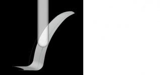
How you think to maintain tool vector normal to surface in complex situation without 5 axis toolpath?

like on the picture, for example

Untitled1.jpg
 
I use this type of path all the time on 3 axis machines. Notice how on the bottom floor the tip of the ball mill is running on the floor, but when the wall goes to vertical it offsets the tool path to compensate for the tool radius.

View attachment 115002

That is maintaining tool axis. Normal to surface would have the tool tilting normal to the floor.


sorry dstryr but i really did not understand your questions?
How you think to maintain tool vector normal to surface in complex situation without 5 axis toolpath?

like on the picture, for example

View attachment 115003

Exactly. You said you were trying to use a 3d path which is what confused me.
 
sorry dstryr but i really did not understand your questions?
How you think to maintain tool vector normal to surface in complex situation without 5 axis toolpath?

like on the picture, for example

View attachment 115003

Well I spent I bit of time in FC last night with your example, and I have to say I don't think it's possible. As best as I can tell 2D Spiral is the only surface strategy that can be directly curve driven (as in, not a boundary), and is also about the only surface strategy that doesn't support surface normal lead and lean.

I can think of a possible workaround, but didn't try it:

1. Create a swept surface along your projected path with a circular profile sufficiently small that your cutter will do only one pass (you'll have to play with the stepover etc.).
2. Use Surface-Surface Trim to create an intersection surface from the sweep and the part surface.
3. On the resulting surface, use an Isoline strategy with surface normal lead/lean.
 
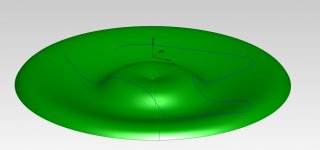
Untitled2.jpg

I was found easier way.

1. Extrude ruled surface from curve (new surface will be normal to machined surface and will follow curve shape)
2. Use Swarf strategy and play with axial and radial offset

But i still can't believe there is no simple straight solution

p.s. sorry for my bad English, hope to understand me well
 
View attachment 115052

I was found easier way.

1. Extrude ruled surface from curve (new surface will be normal to machined surface and will follow curve shape)
2. Use Swarf strategy and play with axial and radial offset

But i still can't believe there is no simple straight solution

p.s. sorry for my bad English, hope to understand me well

Understand you perfectly, nice solution!

It does seem like something that should be easier to do. I am also curious if any of the other CAM softwares have a specific strategy for this.
 
I thought maybe Mastercam have solution because everybody tell stories about famous mastercam tool path control.
Then this should be piece of cake.
 
Although I've never personally done a cut like this, NX gives you the option to have the tool stay normal to the floor with just 1 setting.
Select the walls and the floor and it does the work for you.
 
Although I've never personally done a cut like this, NX gives you the option to have the tool stay normal to the floor with just 1 setting.
Select the walls and the floor and it does the work for you.

Very true, but it's a somewhat inelegant result and lacking in other controls when one uses it. ( from this novice's experience, anyway )

I _believe_ PowerMILL will do what he wants, but I'm not sure I'm getting past the language barrier, here. Is there a model?
 
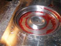
I just used a waterline finish with a 1/32 ball mill and .002stepover...This was just a sample piece I did for UCON when they were looking at a Tormach...
 

Attachments

  • UCONN Test 12-07-0 025.jpg
    UCONN Test 12-07-0 025.jpg
    92.3 KB · Views: 181
  • UCONN Test 12-07-0 023.jpg
    UCONN Test 12-07-0 023.jpg
    94.6 KB · Views: 157
I'm still confused - are we talking about a 3-axis toolpath or a 5-axis toolpath? If I ever grok what you are asking about I can try it in solidcam and report back.
 
Very true, but it's a somewhat inelegant result and lacking in other controls when one uses it. ( from this novice's experience, anyway )

I _believe_ PowerMILL will do what he wants, but I'm not sure I'm getting past the language barrier, here. Is there a model?

Yes with PowerMill you have that control. There are numerous options to work with curves to control your tool path. When working with a single curve you have options for the path to be normal or offset from the curve.
 
I'm still confused - are we talking about a 3-axis toolpath or a 5-axis toolpath? If I ever grok what you are asking about I can try it in solidcam and report back.

my question is about 5 axis toolpath and i think i ask on very clear way. i even upload some pictures as example.

curve driven tool path with tool vector normal to surface


Back
Top