What's new
What's new

Electrical CAD - Something simple, for documentation only

SeymourDumore

Diamond
Joined
Aug 2, 2005
Location
CT
Guys, I know this is a "machining" forum, but will try my luck anyway.

I am rebuilding a machine ( mechanical press ) from absolute scratch electrically and installing all new.

I know exactly what to do, so will not need any "smart" electrical CAD software to simulate or test my stuff.
All I want to do is a simple way to draw my schematics.
I can draw them on paper ( did a few hundred in my school days ) but don't want to go there ever again.
I also am an Autodesk PDSU subscriber, so I do have AutoCAD electrial, but it is the most cumbersome piece of wannabe software
that was kludged together on top of an otherwise awesome 2D platform.
I have Microsoft Visio as well, but that's more of an artsy-fartsy connect the dots thing.

Basically what I'd like to do is place my components ( relays, switches, terminals etc ) on the page, click the connection points and have the software
simply draw the lines as it's normally shown on most electrical drawing printouts with the lines drawn at 90 degrees.

Again, it doesn't need to know what is connected to what and why, just keep the lines as a single entity, I can add connection points, add numbering and all others manually.

I am not necessarily looking for freeware, don't mind plunking down a few hundred bucks for a decent schematic drawing tool.
Is there something out there for a reasonable price?


Thank You
 
Basically what I'd like to do is place my components ( relays, switches, terminals etc ) on the page, click the connection points and have the software
simply draw the lines as it's normally shown on most electrical drawing printouts with the lines drawn at 90 degrees.

This is called autorouting, usually also capable of outputting to a gerber file for the manufacture of PCBs.

There are several options.

CadSoft EAGLE PCB Design Software|Support, Tutorials, Shop <== free upto a certain PCB size and number of layers, The user interface is uniformly loathed.

KiCad EDA <== FREE! , GOOD! , and getting better all the time. Updates from CERN.

DipTrace - Schematic and PCB Design Software <== Good reviews from EEs, especially about the UI. I haven't tried it yet.

.
 
Guys


I meant Electrical software, not schematic capture or routing software.
The project does not have any need for PCB-s.

I have an old version of Orcad for that, but haven't used it for 15+ years.

The issue with any of those packages ( including Eagle ) is that they are completely lacking the electrical symbols ( switches of all kinds, relays, power terminals, motors etc )
that I'd be spending more time creating the library than actually draw the schematics.

Again, AutoCAD Electrical would be a good example of what I'm after, but it's retarded.
E-plan is another, but that is a huge all-involved package, certainly a billion times more than what I'll ever need.
 
Smart Draw :- Wiring Diagram - How to Make and Use Wiring Diagrams
looks promising. Free trial which might be worth a spin but its a cloud subscription so probably not one to keep.

Edrwaw :- https://www.edrawsoft.com/electrical.php also has a free trial and looks to have enough symbols for basic jobs. Not so bad price wise at around $100.

Both are diagram software so lots of cruft for flow charts et al but, hopefully, will have proper "rubber band" and line link functions so you can shift things without loosing connections. One thing that normal mechanical CAD software lacks which makes doing circuit diagrams total pain in the rectum.

Clive
 
Last edited:
It's been awhile since I've had to do an electrical schematic, but when I did I used the free 2d version of Solid Edge. It had a pretty good library of electrical symbols and good CAD tools for drawing the connections.
 
Red

The biggest problem with normal 2D cad tools is what Clive has eluded to, which is that the entities are separate lines, or at best connected polylines.
They are a real PITA to work with when moving either the component or the "wire" if you will.

All of the "real" electrical/electronic schematic tools use "rubber band" type wires, meaning that they stretch along with whatever you're moving.
Once you connect them from pointA to pointB, they get permanently attached to those points and when anything moves, they either move with them
or stretch by remaining attached.

That concept is somehow completely over the head of the developers at Autodesk.....:nutter:
 
Last time I drew a control wiring diagram I used Visio, as I already had it. The Visio connector tool does "rubber band" wiring, although I am always fussing with the way it routes/positions wires when I move the items at the ends.
 
Spend an hour learning AcadE and you'll save several hours of researching the best software and drawing an "unintelligent" schematic. I will say a lot of the AcadE workflow is customizable therefore easier to make work best for you. I don't think you'd need to populate all of the catalog data for relays, switches, etc so using it for the symbols, relationships and counting should still be very useful.

Edit: I started drawing schematics on Acad LT with a premade title block (obviously not necessary for you) but we also had the NEMA schematic library, which I would think grabcad probably has available. Drawing lines isn't that cumbersome once you have the symbols in the correct basic spot.
 
I meant Electrical software, not ...

The issue with any of those packages ( including Eagle ) is that they are completely lacking the electrical symbols ( switches of all kinds, relays, power terminals, motors etc )

Really? 'Cause the example folder in Eagle has a diagram, with those missing symbols.

va22JehY3toJLOvw9pADYpRUaL4KCjN5Bt273CVXLt-U3tKeN8MGVuCk3Z5CfVO03x9qOyUMF0_rILJG6NfykJIGhEHGnW2SYPZTgd4CQyS_sUP9WSYyfHl3HYTXANtq3kf9_da9_3pMIPYcsGpQeIu3SGbOVd5fGZF-i9qkhwsCdN9JoEUhLagHsfvF1ZijnDlKFke2Y_PqxXrajT82IR3XDQDs5navMQmKROPV3ETnXIqZ78G7k6oItdvNukUXe0i1RoXnP3LDANC7vbM4O-DNpti3dduGmFaROeAbfHKQOAL646V2A8SOgHyj1OJS6xIxgczWYnRsNxaQK4KG9qhZe2uppukvylZndOOskMbn9fgo7kdUhzbPWeXS6dyKtdY2Er6FQme41CmuGzvRdF3a2AEt7QK7VRKXTPIxtUPthz0oDwPUgwndot_5d66B5zwjs7ZP6oSzcoaUPBM7lTxntq_TFJ3s4GnPSeOTU_bJveYaGFm-rLIHSVXBgqG1KpEsU1i65mlyDXXBZ3zFdbmy2vP2m6GTNQ9DWRTRohji5xM8DFvRkxHJHhUXzdgBvB54=w1050-h803-no

.
 
Red

The biggest problem with normal 2D cad tools is what Clive has eluded to, which is that the entities are separate lines, or at best connected polylines.
They are a real PITA to work with when moving either the component or the "wire" if you will.

All of the "real" electrical/electronic schematic tools use "rubber band" type wires, meaning that they stretch along with whatever you're moving.
Once you connect them from pointA to pointB, they get permanently attached to those points and when anything moves, they either move with them
or stretch by remaining attached.

That concept is somehow completely over the head of the developers at Autodesk.....:nutter:

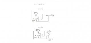
Solid edge has a special tool called a connector that does exactly what you are describing. When you move a component the connector stretches to stay attached. It also has an option to jump over other lines when you have to cross over.

Here is a simple one I made for some conveyors with DC motors(sorry about the low quality image. For some reason Solid Edge outputs really low resolution jpegs. I could't attach a pdf.):

Electrical schematic 2014-02-04.jpg
 
Really? 'Cause the example folder in Eagle has a diagram, with those missing symbols.


.


OK, I now stand corrected, thank you.
Took a while to weed through the German-only description, but found a good deal of the components I need.

Spent the better half of the day going through AutoCAD Electrical, and I have not yet changed my mind about it being cumbersome at the very least,
so I'll play with Eagle a bit tonight. Looks like it does exactly what I want, tough the interface does .... well suck a bit.


Back
Top