What's new
What's new

Solidworks , 3D guidance or help on making these dies.

bmikkalson

Hot Rolled
Joined
Jan 20, 2010
Location
St, Paul MN
Hi, I'm a total self taught solidworks guy, I've been able to get by making simple parts and such. Now I have a design and I don't even know where to start or who I would call. Using a student version of SW

Nit expecting some one to do my home work for me, I need some guidance, I don't mind putting in the work .
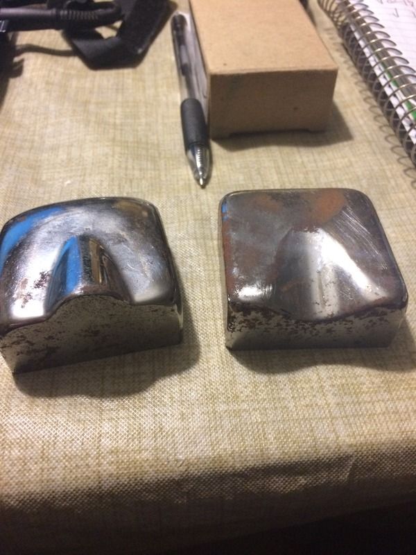
I am having trouble creating the reliefs and blends in these thumb nail dies.
Where and how do I even start?

My ultimate goal is to machine my own. But that's down the road.
 
Could try with a simple block extrusion, then insert a plane at an angle to draw the profile of the protrusion on and extrude it out. Then start adding fillets and chamfers. Use a similar process to create the female half, but make an extruded cut
 
I agree with the other Doug. If you are trying to replicate what is there, I would have them scanned.
You could have the scanning source provide cross sections so that you have a little bit of control while modeling.
 
guess it depends on how close your trying to match whats in the picture.

If just eyeballing it, draw the profile and then do a tapered cut/extrude.. throw some fillets on it, and that should be good enough.
 
Looks like half of a conical boss.
Measure height of male boss.
Measure width of male boss at widest end.
Measure length of male boss as best you can.
Approximate radii with radius gages or w/e works.

Model a block in Solidworks that suits the die size.
Model a cone into the block with center of base diameter at midpoint of one edge of the block as shown in the pics.
Fillet the tip of the cone to the appropriate radius to round the point.
Fillet the joining edges around the periphery of the boss.

Create a second die block by subtracting the first from a new block object.
Offset the surface whatever material thickness to create the appropriate gap. Assuming it's a uniform gap. I dunno.

Seems like "eye balling" with a few reference gages would be good enough for a sheet metal hammer die. More important that they match eachother for good die life than it is for them to be a precisely exactly correct shape, I would think.
 
There are youtube videos.
The solidworks support website has fairly active forums, some subforum there might be of help.
There are various tutorials, including some included with the new releases.

How to digitize - you have, say, a bridgeport with a DRO? And, say, a 3D Taster? (Haimer being a famous one) You could (slowly) manually probe at smallish intervals along the shapes to make splines - say 0.010 by 0.010 by 0.001 in Z. (Getting the taster to not slip on the angles will be a pain.) Or use a Faro arm. A renishaw or the centroid wired probe are both laterally stiffer, they'd be good to use. (Centroid even sells an add on package to support this.)

Given this data, make splines, then loft them together.

The merit of this is that you can build the Dies, try them, fiddle with them by adjusting the splines, and repeat.
 
The dies shown are power hammer dies for metal shrinking of sheet metal. These type dies were usually developed by trial. Make a set using the best guess of shape, then "tune" the dies by observation of contact areas during testing.

An issue here is how will the subtle contours be determined by measuring? There are all sorts of variable contour fillets.

My suggestion is to have them scanned.

I know what the dies are, there for my pullmax, I don't have a digitizer and probally not gonna get one real soon. And I'm gonna guess, it's big bucks to have done.
 
There are youtube videos.
The solidworks support website has fairly active forums, some subforum there might be of help.
There are various tutorials, including some included with the new releases.

How to digitize - you have, say, a bridgeport with a DRO? And, say, a 3D Taster? (Haimer being a famous one) You could (slowly) manually probe at smallish intervals along the shapes to make splines - say 0.010 by 0.010 by 0.001 in Z. (Getting the taster to not slip on the angles will be a pain.) Or use a Faro arm. A renishaw or the centroid wired probe are both laterally stiffer, they'd be good to use. (Centroid even sells an add on package to support this.)

Given this data, make splines, then loft them together.

The merit of this is that you can build the Dies, try them, fiddle with them by adjusting the splines, and repeat.

Hmm, the Dro idea is a pretty good one. Thank you .👍
 
Exactly.....

These dies are not simple one hit type like many sheet metal dies. These are used to feed the edge of a panel into an oscillating hammer a couple inches raising something like a tapered bead at he panel edge. Raising the bead should pull the panel in from both sides, you want the bead formed by as little stretching as possible. When the panel is fed out of the dies you hope the bead will be crushed into itself thickening the panel in that area and shrinking or decreasing the panel's area.


The dies aren't the most effective way to shrink panels, they're relatively inexpensive compared to better methods.

The dies also need a bit of operator expertise to work efficiently.


What are you thinking is a better solution to shrink a foot into a panel ?
Thumb nail dies are a amzing tool.

Besides a eckold, I can think of no other substitute.

Any way , back to the problem at hand, modeling these in solidworks .
 
Could try with a simple block extrusion, then insert a plane at an angle to draw the profile of the protrusion on and extrude it out. Then start adding fillets and chamfers. Use a similar process to create the female half, but make an extruded cut

Ok, gonna mess with this tonight .
Thanks
 
Looks like half of a conical boss.
Measure height of male boss.
Measure width of male boss at widest end.
Measure length of male boss as best you can.
Approximate radii with radius gages or w/e works.

Model a block in Solidworks that suits the die size.
Model a cone into the block with center of base diameter at midpoint of one edge of the block as shown in the pics.
Fillet the tip of the cone to the appropriate radius to round the point.
Fillet the joining edges around the periphery of the boss.

Create a second die block by subtracting the first from a new block object.
Offset the surface whatever material thickness to create the appropriate gap. Assuming it's a uniform gap. I dunno.

Seems like "eye balling" with a few reference gages would be good enough for a sheet metal hammer die. More important that they match eachother for good die life than it is for them to be a precisely exactly correct shape, I would think.

Ok, gonna try to break it up into .250 segments .
Yes eye work is close enough.


Back
Top