What's new
What's new

Where do you set your offsets, as a rule?

litlerob1

Diamond
Joined
Nov 4, 2013
Location
Utah, USA
I'm having a little trouble and wanted some opinions. I work with a woman programmer who is great but she does some stuff her own way. Bat shit crazy but who am I to judge.

Example, when I post code the operators KNOW that X,Y zero is usually the center of a 3axis mill part, or the far left corner, or if a turned part always on center of rotation and Z zero. I am having a tough time figuring out why my coworker changes, sometimes a milled part that the close side is Y zero, or sets it that way in the software, to be weird or its easier?

Question; do you guys consistently make the WCS the same, or is it just me. Of course there are parts that you absolutely cannot, so I get involved, right?

Robert
 
I try to make the WCS consistent, but there are times it just can't be. The most difficult part of my job has been fixing the last guy's random messes though. Inconsistencies all around, terrible feeds and speeds, bad setup notes, multiple setups for (something that should be) three simple operations.

Anyway I digress. I try to use left side of part/stock against the fixed jaw. If it's an old print (part not in SolidWorks or the old print just keeps following the part around), I follow the dimension lines to try and make it easy. Sometimes I get questioned about that too though. We have a standard Excel setup sheet for each machine, so it's easy to tell which program to run for which machine (we only have two VMC's and one turning center).

The next step is to standardize vise locations on our subplate so if the part gets run on that machine, load the program, machine probes the stock based on the built-in offsets, and we eliminate stops and hand jogging the probe around. Who knows when that'll happen though.
 
I think your coworker should do her own setups for awhile, it would make her a better programmer. I'm in line with how you reference parts, and try to be as consistent with it as possible even though I am a one man shop.
 
Recent example ( to me this so strange, I can't even grasp the logic).

Bolt hole circle, with counter bores??? 8 holes. Her X Y zero was at 1:30 45 ° the second hole of a hole that wasn't there yet, I mean my trig is okay but????

Only thing I can think is rotating original geometry from 12 o'clock hole and somehow not changing the coordinate system, but our suckware does that anyway, so how! Why?
Robert
 
I TRY to be consistent with my zeros... I really do, but I'm not...

Sometimes Zzero is the top, sometimes its the bottom, sometimes its some feature randomly in
the middle.

XY's.. That's all over the map.. Sometimes its the actual vise corner, then machine jaws in place and run part.. Sometimes
its center of part, sometimes its the top left, sometimes the top right, sometimes its a feature in the center, occasionally
its a point that isn't even within the travel of the machine.

4th axis stuff, still all over the map.. Z's, depends, top of a feature, top of the round part, center of the round part...
Even the XY's can change and be not on center, depending on what it is...

I've tried to standardize, and I just haven't been able to do it successfully... Sometimes the part tells you where the zero's
should be, and convention goes out the window.

One thing that always remains.. zero's on the fixed jaw!.. Though I have a few times put the zero on the moving jaw, and I had a reason,
and it sounded good at the time, but I can't for the life of me think of what it was. And X zero always center of rotation on turning
work... I've done a very very small amount of parts where it wasn't, and I didn't like it at the time, or now.
 
I usually try going off a rear corner either left or right, or a specific feature, like a bore/boss. Depends how the drawing is dimensioned.

I suppose it also matters what the part is.

Simple part and cheap material? I'll go from center, top of the part. IMO, it helps the machine operators a bit so they don't have to do any math figuring how much to offset for stock. They just use the block cycle on the probe, then pick up and offset Z 10 or 20 thou. If you're cutting 5 sides it doesn't matter too much on the first OP, unless your saw is inconsistent. Just gotta make sure the material size is what the program says.

Downside is your program coordinates usually don't match the drawing. Makes it more difficult to check as you're running the part.


If it's a 1-off modification or expensive part? I'll try to match the drawing so they can check the program coords easier as they're running the part.

Either way, I just need to make sure it's spelled out clearly in the program header (or setup sheet) and it runs pretty smooth.
 
Wherever the spindle is located when the milling machine homes the table is probably a good place for X0Y0. If you have to machine a part that is close to the full size of the table travels, that is the simplest place to put it. It helps make approximating the position of the stock (with a tape measure) easier when arranging the clamping so you don't get an overtravel alarm because you inadvertently ran out of travel because you didn't know the part extents used in the program had nothing to do with the real world travels of your machine.
 
Wherever the spindle is located when the milling machine homes the table is probably a good place for X0Y0. If you have to machine a part that is close to the full size of the table travels, that is the simplest place to put it. It helps make approximating the position of the stock (with a tape measure) easier when arranging the clamping so you don't get an overtravel alarm because you inadvertently ran out of travel because you didn't know the part extents used in the program had nothing to do with the real world travels of your machine.

So if you are building a part in a vise in the center of the table you set XY zero at the home position? Seems like a lot of work, and hard to track. I know you run Haas equipment Hu, but that seems like asking a lot from the operators, but I guess thats one way to go.
 
I program from the WCS zero, after tool changes, and.before approach, so the operators can take out their scale and think oh distance to go is the same. Glad I started this thread, I just thought everyone did it my way :D
 
So if you are building a part in a vise in the center of the table you set XY zero at the home position? Seems like a lot of work, and hard to track. I know you run Haas equipment Hu, but that seems like asking a lot from the operators, but I guess thats one way to go.

I've done it.. Zero at home...

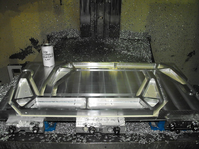
This part.

5331335377_98da6b4ef2_z.jpg


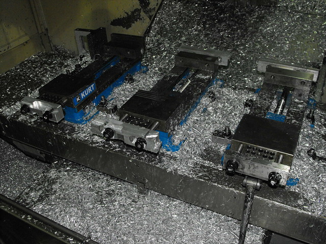
5332569866_517a1ec2d7_z.jpg


I always keep the fixed left Y+ corner of each vise in fixture offset 21,22,23.. So it only took a few minutes to draw up the
table and vises.. Then I figured out the spacers I needed on my jaws, where I could and couldn't cut through etc...
And by that time the part(s) where on the vises, and
everything was in place to just simply leave the zero at the machine home. So that is where it stayed..

Normally, no, that doesn't make sense.. unless the table travels and limits and/or T-slots/fixture holding on the table are important
to making the part. If you have one fixture that goes in the same place everytime, fine.. If everything you do is off of a point on
a fixture plate.. Fine... But generally, that's a pain in the ass...

I know where the corners of my vises are, so 85% of the time I'm never even picking up offsets.

Recent example ( to me this so strange, I can't even grasp the logic).

Bolt hole circle, with counter bores??? 8 holes. Her X Y zero was at 1:30 45 ° the second hole of a hole that wasn't there yet, I mean my trig is okay but????

Sounds like a "programmer" that has never touched a machine, not a machinist that has to deal with the BS... If its a hole that is already there,
and you are picking up on a dowel pin.. I'm fine with that.. Just a random hole, that isn't even there yet.. That's just stupid.

Does the "programmer" even understand that a "Zero" has to be picked up somewhere? Is this a cad school jockey that pulls on files and
handsaws because its easier than pushing? Is the "programmer" just being inept so they can be promoted to the CMM department where
they can screw up things that are already actually correct?
 
So if you are building a part in a vise in the center of the table you set XY zero at the home position? Seems like a lot of work, and hard to track. I know you run Haas equipment Hu, but that seems like asking a lot from the operators, but I guess thats one way to go.

No I didn't mean that is where I set home, I mean, since that position is the back right hand corner of the part on my Haas, then I would use the back right hand corner for the primary datum all the time, if the part is rectangular in nature. If I have to flip the part, then the datum goes where it must go.

I usually place my CAD models in the X-Y- quadrant. If I had a machine that homed X in the other direction, then I'd switch my cad model to X+Y- and use the datum on the back left hand corner.
 
Greetings,

My zeros are usually left rear, against the solid jaw, but regardless of where they end up, I always put a header block into the code explaining *where* all the zeros are, along with whatever jigging and stop info is needed. I'm the only setter, but if it's 24 months since the last time I did this part, I'll have no idea what I did last time. Thus the notes. (Like 'watch your Z on T3, or you'll smash the rear left clamp'.) Little things.

FWIW,
Brian
 
Recent example ( to me this so strange, I can't even grasp the logic).

Bolt hole circle, with counter bores??? 8 holes. Her X Y zero was at 1:30 45 ° the second hole of a hole that wasn't there yet, I mean my trig is okay but????

Only thing I can think is rotating original geometry from 12 o'clock hole and somehow not changing the coordinate system, but our suckware does that anyway, so how! Why?
Robert

Sounds like a classic "I know how to program!" (but I have never actually ran a machine or made setups)

I don't think I have anything I use as a standard, other than trying to use the fixed jaw as Y0 whenever possible and Z0 at the top of part. As Bob said, I might have used the moving jaw once or twice for Y0, but I would guess (same boat as him, can't tell you now why I did that... :crazy:) I loaded the part, picked up offsets and it was a one-off thing. I would just say to ask her. Depending on what type of person she is you can use your own judgement on how to approach her. Maybe just something casual like "Hey I see XY0 is this hole (point to print), can you give me a dimensions from the edge of stock?" Hopefully that will start the conversation of "Oh, I didn't realize you are starting with xx size material, or Is there an easier way for you guys at the machine, etc, etc"

edit: Lately I have been trying to use the datums of the part as my zero, if possible.
 
Mine are all over the map too, but my operators have a setup sheet that shows where the datum is.
4th axis stuff Z zero is always center of the part.
3 axis, I try to keep it back left corner of the stock, sometimes back right corner.
Round parts x y is always center of the part.
 
just like most of you no one set way for setting the zero. really just part dependant.

most vise work upper right corner top of stock, if has fip, deck and then probe a feature or edge and bottom of part.

if I have symmetrical plate work using reamed pins to flip I use center of pins and top of sub-plate, or if holding down with double stick tape top of tape (plastics).

always changing
 
Throwing onto the pile:

Op1 datums are 95% center of stock and say .01 or .02 below top
Op2 datums are back left or back right corner based on datuming from the drawing or occasionally a thru bore on the part
Op3/side ops will usually be top surface and back left/right corner based on drawing datuming

Round parts will be center of stock

Tape down work is bottom of part (top of tape is a consistent .008")

4th axis work is center of rotation and 1/8" off our dovetail fixturing

I try to keep it consistent and everyone gets a setup sheet for the job before starting so there is no confusion.
 
3 Axis OP1: X, Y is center and -.025 in Z from the top.

OP2: "X" is center "Y" is back jaw and the base of vise or top of parallels in "Z" considering that face should be finished.

4th Axis is always the center of rotation and usually the face of dovetail or fixture for "X"


That's my go-to but obviously can't always happen...
 
If running more than one part the zero should be the fixed stops.
Front of the vise is movable but the lower left corner makes sense to many on the CAD?CAM side but screws you for making parts.
One piece, you have to pick it up anyways.
Who cares as long as the instructions come with the job but if you don't use the fixed locating sides there should be a big red note.
If your incoming stock has a tolerance on say vise clamping axis width and you use this as zero let's hope you have a lot of tolerance to throw away.
Otherwise you have to know the deviation from zero on your setup part and comp the zero accordingly.
That is just painful and time consuming but sometimes the print datum is not your fixed locators in the mill which just sucks.
Then your op is off and you have to run way-way inside as the tolerances stack up.
It blows when the second op depends on the first and the third depends on the second. Now #1 had better be held to 1/10 of it's actual tolerance.
We end up in this problem sometimes so a +/-.002 tolerance on a thickness or width must be held to 2 tenths or we will be screwed down the line.
Bob.
 
It sounds as though your programmer doesn't know how to setup WCS or move the part around in the software. What software are you using?

I try to stay consistent, but there are many special cases where I have to deviate from the norm.
Usually:

1) op1, center of the stock, top of stock -.010 skim cut
2) op2, 50/50 either center of the part, or back corner.
if I use a corner, I try to make it the same datum as the drawing. Makes it easier to read thru the program and see whats going on.

Using the center of the stock helps because there is no need to calculate to account for stock, just find the center.

Whenever the part setup allows it, I try to incorporate probe routines into the program to pickup every part, really helps to counteract varying vise pressure moving the part around away from the original offset.


Back
Top