What's new
What's new

How to remove the ram and the knee on a Van Norman 22L

Paolo_MD

Stainless
Joined
Apr 6, 2013
Location
Damascus, MD
I've just purchased two old Van Norman 22L milling machines (for the overall details of the move etc. follow this thread) and I need to remove the ram and the knee in order to move them.

My plan is to leave overarm, head and motor mounted on the ram, remove the rear stop pin, crank the ram forward till the pinion disengages the rack, push it forward till everything exit from the dovetail, while holding the ram assembly with an engine hoist.
From the pictures on the manual I cannot see clearly what type of gib is there (e.g. tapered, or flat with adjusting screws on the side) and I'm wondering if it would be better to remove it once the pinion disengages the rack.

Am I missing anything?

Once I've removed the head, the vertical path for the knee is clear and, after removing the Z-axis stops I should be able to lift it till the elevation screw disengages. At that point I should be able to lift it straight up till I clear the dovetails.
And, yet again another question regarding the gib: shall I leave it in place, or is it better to loose it? My concern with loosening or, even worse, removing it, would be that I'd lose the vertical alignment and risk to damage the feeds splined shaft and elevation screw.

Does it sound right?

I'm planning to start the disassembly tomorrow after work. Therefore, I'd appreciate any comment from any member who has taken apart his or her own one.

Thanks!

Paolo
 
It's hard to believe I'm the first one doing this...

Just bumping up this thread. In a couple of hours I'll be heading to the milling machines to disassemble them as described in the earlier post.

If you have removed the ram and/or the knee of one of these machines, I'd really appreciate if you could provide me with tips, warnings, etc.

Thanks!

Paolo
 
No experience with VN, I have a B&S that came to me with the table off to fit through a doorway, might be similar. The main damage to mine was 2 things-the oil lines have a hook to oil the gibs, both were damaged. Looking from the ends these are visible with a flashlight. The people must have allowed the table to tip up and hooked the lines and damaged them. The other thing which is much more major is the crack in the bracket that hold the screw for the table. The screw was allowed to hang from the handle end bracket and cracked. Removing the screw before removing the table would have removed this issue. The gib on mine is screwed on from the ends, I would leave it in place until the table is off and then you can just pick it up if it is like mine.
Joe
 
Thanks, Joe.
My plan is to leave the table on the saddle and remove the whole knee assembly in a single block. For lubrication everything should be self-contained. Definitely, I'll drain the knee before removal.
On the VN 22 the power for the powerfeeds is provided by a splined shaft parallel to the elevation screw: if I remove everything from the top, I don't foresee any major issue.

We'll see soon.

Thanks!

Paolo
 
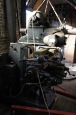
Ram successfully removed

I'm finally back hole cooling off after a few hours in steamy heat, tackling the ram of the first of the two Van Norman.

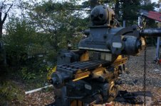
Today I've tackled the newer one (Serial #7434 - very late 1952) with 50NMTB spindle.

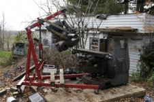
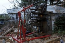
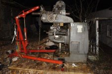
Here is the result:

NEX_5_DSC1358.jpg

Essentially, I've followed my initial plan with only slight 9logical) modifications.

After moving forward the ram as much as I could with the crank, I've pushed it a few more inches with a crowbar and pieces of wood.

NEX_5_DSC1354.jpg

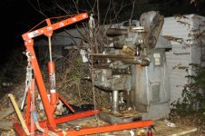
Then I've set up a rope harness and partially lifted it with the engine hoist:

NEX_5_DSC1353.jpg

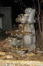
Finally, I've placed two pieces of 4x4 longitudinally on the table and two pieces of 2x3 parallel to the ram, one at each side of the rack.

NEX_5_DSC1356.jpg

While playing with both the elevation and the tension on the engine hoist, I've dragged the the ram all the way forward using the transverse table movement (repositioning a few time the table and the blocks and pulling the engine hoist).

For the last inch or two I resorted once more to the crow bar and pieces of wood: although the ram was fully supported by both the hoist and the table, I didn't feel very comfortable turning the crank the last few turns.

The whole ram assembly, with motor, overarm (but without any overarm support) and milling head on this machine weighs ~850lb.

Tomorrow evening will be the turn of the knee assembly and the other mill.

Paolo
 
Another point, before I forget: removing or not the gib before removing the ram is a moot point: the gib is held in place by the two cams that lock the ram. Therefore, one should remove the cams first (I'll probably have to do that, since the front one doesn't lock well anymore and, probably, it needs to be adjusted, or the gib re-scraped and both cams readjusted).

Paolo
 
Paolo, as noted in one of the other threads, I'm pretty sure the machine in the photos you just posted is a model #24 of some flavor (22LA, 22MA, etc)., however the serial number plate contradicts that. Got some followup questions for you over there. Your other machine is definitely a model #22L.
 
Paolo, as noted in one of the other threads, I'm pretty sure the machine in the photos you just posted is a model #24 of some flavor (22LA, 22MA, etc)., however the serial number plate contradicts that. Got some followup questions for you over there. Your other machine is definitely a model #22L.

sfriedberg,
I've replied extensively in the other thread: I'm quite positive that it is indeed a 22L and not a 24.

Paolo
 
Paolo,

Great job on the ram. Excellent write up!

I think that I would take the table off next, rather than try to remove the table, saddle and knee together.

Cal
 
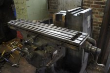
Knee block succesfully removed.

Thanks, Cal!
Too late for your suggestion, but everything worked fine, almost according to the plans, but failed in the short-cuts.

Here are the essential findings:
1) The leadscrew doesn't disengage at the top end of the travel.
2) It is practically impossible to remove the the gib while the knee is still on the column.

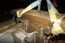
Let's go in order. First I've cranked up the leadscrew as far as it would get, and I was very surprised to feel a stop. With two straps around the table, I've secured the assembly on the engine hoist and unscrewed the flange at the base of the leadscrew.

NEX_5_DSC1359.jpg

Then, I continued lifting till the splined feeds shaft was completely disengaged: at this point I didn't need to fear any more any lateral movement. Therefore, I attempted to unscrew the gib.
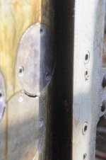
To my dismay, the gib didn't want to move even after removing all the screws. I therefore continued the lifting operation and uncovered why the gib stayed put: it is crossed by a large pin of the knee lock:

NEX_5_DSC1364.jpg

The sub-assembly was successfully removed from the top. I used the transverse table movement for balancing it: with the table almost all the way to the back, with the straps arranged as I did, the table is level.

NEX_5_DSC1365.jpg

The whole sub-assembly weighs almost exactly 1100lb.

For the other mill I will lower the knee all the way, disconnect the flange of the elevation screw, adjust the the table to be even in the longitudinal position and close to the column in the transverse position, wrap the straps around and lift it all the way with the engine hoist.

One of the main reasons why I'm taking it apart in big chunks is that the place is pretty unpleasant: this is an eviction sale. The guy who rented the place till a few months ago was living there with many cats and dogs, sometime without letting the animals outside for several days in a row. The guy who has a woodworking shop next door and is going to rent that place did a lot of cleaning, but much more is still to be done.
Combine the stench with heat and humidity, and you get a mix that makes me trying as hard as I can to get as much as possible done in the shortest time.
To be also considered that I live and work ~50 miles from the place where the machines are. Yesterday and today I managed to go to work very early, leave around 3:30, arrive there around five and do something till ~7:30 when the guy rightfully wants to go home.

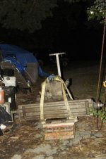
Sunday I should be able to borrow a decent size trailer from a friend, allowing me to move more stuff more quickly.

So far, I brought home only the knee assembly.

NEX_5_DSC1380.jpg

Next step, hopefully Monday.

Paolo
 
Guys,
Apologies for letting this thread getting cold so fast, but I've been quite busy at work and hauling home cast iron (today, after work, we'll move the Putnam lathe to Tuckahoe).
Essentially, the disassembly of both machines went smoothly with practically the same technique. I would therefore claim that this procedure would work for any 22L machine, since the oldest one was produced during the first year of production (1940 SN 5097) and the newest during the year before the last year of production (1952 SN 7434).
Here are the only three improvements to the protocol that I've applied when disassembling and moving the second machine.
1) Once the ram is out, I've removed the rack (it is secured by three hex socket head screws), so that I now have a nice and flat surface at the bottom.

2) As mentioned earlier, with the second mill, I first cranked the table to the very bottom, removed the flange and lifted the table/knee assembly with the engine hoist. The table should be cranked almost all the way to the column, roughly 2" before the end of travel. It's useful keeping adjusting it while lifting the table, since first you have to compensate for the drag of the column.

3) Once the table is almost all the way out, it is very useful to loosen the gib, allowing the saddle to tils slightly. Otherwise you risk to lift the base together with the assembly.

More details on the move and differences between the castings of the early and late specimens will be presented in my other thread, once I find a few minutes to go through my pictures and take a few more.

Paolo
 
Re-Assembly Process

Apologies for neglecting this thread for so long, but I didn't have much to report. finally,
last night I've started reversing the order of the operations by putting back the knee, saddle and table assembly on the column of the younger machine.

As I've mentioned in my other thread, my immediate goal is to reassemble the machine in order to assess the wear and the functionality, something I couldn't do at the original location.

This part of the reassembly went much smoother than I anticipated, most likely thanks I was under much less time pressure and had more time to think.

Essentially, the major trick was to remove the Z-axis stop and the gib (the stop rod would interfere with replacing the gib when the knee is on the column.

NEX_5_DSC1733.jpg

Without the gib, it is enough to raise the assembly just high enough to clear the splined shaft.

NEX_5_DSC1740.jpg

Then I held the assembly against the column with a simple strap and pushed the the right slide completely against the way by clamping the top edge of the knee casting to the column.

NEX_5_DSC1741.jpg

NEX_5_DSC1743.jpg

After that, all you need to do is to bolt on the gib (it's better to screw in again the Z-axis rod at this point, to ensure perfect alignment with the gib, something I failed to do), lower the Z-screw, and bolt the flange to the base casting.

NEX_5_DSC1751.jpg

Note that you need to remove the cast piece holding the Z-axis stops, in order to have full access to all the gib screws.

The next step, hopefully soon is to clean and test the ram/head assembly and to mount it.
 
It's time for another update.

Last Sunday I found some time to wrestle with the ram/overarm/head assembly.
After some cleanup and testing of the gearbox and head (more about that on the other thread), I've finished the overall assembly.
Due to the limitation of movement of the engine hoist on the small wooden platform, I had first to rest the assembly side-wise on the table.

NEX_5_DSC1761.jpg

After that, I've raised it over the column and rested on the column and a couple of 4x4 pieces on the bed.

NEX_5_DSC1764.jpg

The third step consisted in re-positioning the chain so that I would support only the front with the hoist, while the back would be supported by the table.

NEX_5_DSC1768.jpg

Finally, by playing with the table and the hoist I've engaged the dovetail and managed to push the ram back with the Y/Z travel (axis designation with the spindle being in the vertical/horizontal position).
Positioning a rod or something similar at the front edge of the table, in order to stop the sliding of the wooden blocks, helps significantly.

NEX_5_DSC1770.jpg

Once there was enough engagement of the ram, I've put back the rack and, once the rack contacted the pinion, I cranked the ram back directly with the crank.

NEX_5_DSC1776.jpg

t took a while, but everything went smoothly, without any significant surprise.

Only two brief notes here regarding removing the cover from the gearbox:
First, the shifters should be located more or less in the middle (B2), otherwise they interfere with the casting.
Second, you definitely need the gaskets and they should be in good shape. Probably, you can replace them with a bead of RTV.

Paolo
 
Some more heavy-lifting...

(at least for my standards)
Last Sunday I've managed to find some time for completing the reassembly of the main components of the mill.

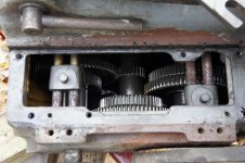
The first step, while closer to the ground, was to inspect the gearbox, do the necessary repairs, and test the spindle.
The shifters didn't move freely. The rust above the cover made me suspecting the worst. I managed to open the cover by dead-blow-convincing the ABC shifter to move enough to clear the casting and found that the actual cause was only some rust on the rods on which the forks travel. Everything else was in very good shape, probably thanks to the fact that the gearbox contained some oil.

NEX_5_DSC1754.jpg

After scraping off the rust I and tipping it with K-1 kerosene, I closed it and tested the spindle with a VFD.

Then I lifted the assembly and re-assembled it to the rest of the mill (more details in my other thread).

NEX_5_DSC1771.jpg

The last effort of the day (better said of the night) has been wrestling back and forth the assembled mill with the pallet jack to move it in the final position.

NEX_5_DSC1776.jpg

The knee is filled with kerosene and this weekend I'll be testing the feeds.

If there is nothing really terrible that needs to be addressed right away, I'll start building a shed around it, making sure that any of the walls could be easily removed (for better access to the machine, without compromising the rigidity of the structure.

NEX_5_DSC1777.jpg

Paolo
 
It's been 2 years, but thank you, Paolo, for documenting your Van Norman 22L disassembly. I've recently purchased a 1941 vintage 22L and will be attempting to remove the head, ram, table, and knee this week.
Many of my initial questions have been answered by your thread, but I'm sure new concerns will arise as I go through the disassembly process. Hopefully, you are still an active member and will be able to help out!
Paul
 
Hi Paul,
I'm glad that this thread was of some help to you. Yes, I'm still more or less active on this forum, compatibly with work and other commitments.
Good luck with your mill!

Paolo


Back
Top