What's new
What's new

K&T 307 S12 main motor rotation

Timbosama

Aluminum
Joined
Jul 23, 2014
Location
Texas USA
Is there someone who can tell me the correct rotation direction of the belt end of the main motor for a 307 S12, please? Does it even matter (I'm assuming that it runs something that doesn't want to turn backwards)? Does the spindle direction switch actually make the motor change rotation direction?

On initial startup of mine -- with the feed motor turning in the direction indicated by the arrow on the knee -- I discovered that the main motor had been re-wired to run at 230V, even though the rest of the machine is wired for 460V. :angry:

I didn't smell any smoke, so I've got my fingers crossed.

So I'm reconnecting the main motor for 460V, but I don't know which direction it is supposed to turn, or if it even matters.

Thanks for any help.
 
Older K&T mills have a nice ARROW cast on the clutch pulley. Yours is likely too modern to have a clutch, but surely it still has a pulley/sheave
 
Older K&T mills have a nice ARROW cast on the clutch pulley. Yours is likely too modern to have a clutch, but surely it still has a pulley/sheave

Hi, John,

I posted too soon.

I figured out the wiring diagram: the main motor reverses with the spindle rotation switch. I should call it the spindle motor rather than the main motor. It doesn't have an arrow on it, because it can go either direction.

The feed motor in the knee has to turn clockwise when facing the machine, (there is an arrow on the front of the knee) and I had that right already. It turns out to be wired for 230v, too, now that I've found the motor connection box.

However, the powered ram is set up for 460v.

A previous owner appears to have reconnected some but not all of the motors to run at low voltage.
 
I'm finding with my S15 that it is a fair amount of work to reconfigure a machine from 240 t0 480 or visa versa. You should look at the ratings of the motor heaters and make sure that they match the amperage draws of the motors on the input voltage. At the lower voltage the amp draws would be twice as much and the heaters can over heat and drop out the control circuits. The heaters are for protecting the motors from over heating. Since the motors are pretty specialized wouldn't be inexpensive to replace them. There is the coolant pump motor to consider too. When running the mill in the cw direction, the main motor should run, from the pulley end, clockwise. I am not sure if the hydraulic pump will act the same way if the main motor is running backwards. Seems to me the machine wont work if the hydraulics are not running right. (Issues I am trying to work out now with my machine, not enough hydraulic pressure). If your machine has a power draw bar that motor needs to be addressed also for correct voltage. Good luck with your project. Tim
 
Thanks, Tim. I have all four motors (spindle/main, feed, ram, and coolant) wired for 230v now, and all the heaters are running cool. But the main spindle is running slowly, not at all, or only with an assist to get it spinning.

Also none of the power feeds work at all.

Does the spindle motor run the hydraulic pump? I assumed it did until I saw that it is supposed to run both directions. Now I don't know. it seems like it would have to.

The knee and column fluids were at the full lines when I changed them out, but they are both low now that I've run the machine for a few minutes. I'll top them off and see if that does anything.
 
Do you have any of the manuals? Especially the maintenance manual? If you need copys of the manuals I think you can download what you need here: Kearney & Trecker Co. - Publication Reprints | VintageMachinery.org There is some pretty good explainiations of the hydrolic pressures and where to test at. Your description of the spindle action sounds like my situation. System pressure is supposed to be 200 lbs, and there is a delay pressure for about 5 seconds before the spindle engages and comes up to speed. Also almost all the control circuits wont work with out the spindle operational. Even the knee power feeds wont run on power feed if the spindle isn't engaged. I can explain more of that sys if you need. Tim
 
There is some pretty good explainiations of the hydrolic pressures and where to test at. Your description of the spindle action sounds like my situation. System pressure is supposed to be 200 lbs, and there is a delay pressure for about 5 seconds before the spindle engages and comes up to speed. Also almost all the control circuits wont work with out the spindle operational. Even the knee power feeds wont run on power feed if the spindle isn't engaged. I can explain more of that sys if you need. Tim

OK, I brought the knee fluid back up to full, and now all the feeds and rapids work. The drip glass on the knee now shows a drip when the machine is on.

While I was typing my last message, the column drained back down to the full line. The drip glass on the column goes completely full when the master switch is pressed, so I have good flow to it, at least.

So the spindle is the only thing still boogered up right now. Most speeds it doesn't turn. Some speeds it sort of freewheels at about 20 RPM, and it can be stopped (and even spun backwards) with very little effort. A couple of speeds it will run slow for 5 or 10 seconds, then come up to what looks like the right speed. This is the case for LH and RH directions.

I guess I'll read the hydraulic testing stuff now. Blech.
 
My machine won't run the spindle unless the hydraulic system pressure it up around 200 psi. There is a switch by the pressure regulator body that electrically allows the spindle clutches to be engaged to activate the spindle. The electric sol is also mounted on the pressure regulator body (housing). My machine had a broken spring in the cavity that controls the system pressure. When this was replaced (local hardware store) I got sys pressure up to 185. The spindle would activate. Does your machine activate the table feeds when the spindle does not activate? or do you have to activate the direction lever and then manipulate the rapid lever down to move the table? or up to feed direction rapidly? I think if the table will move with out using the rapid lever, then the column sys pressure is OK and that your having a problem with the clutch delay hydraulic system.
 
My column constant pressure is only 150psi. I spent today swapping out spacers, trying to get it to the 200 the manual specifies. At 180 psi, it would eventually get into gear in all speeds. But it took multiple spindle start-stops to make that happen.

The feeds seem to work so long as the spindle switch is on. Mostly. I'll check the delay pressure and see if it is out of whack.

Short version, I'm still messing with it. Thank you for all of the suggestions.
 
I've learned an interesting thing about my machine. It has to do with the hydraulic pump for the control circuits. It has to pump in the same direction regardless of motor direction. It uses a valve, for lack of actually knowing the term, I would call it a shuttle valve. It keeps to oil flowing in the passages regardless of the direction of pump gear rotation. My machine recently had not pressure on the hydraulic system so on a whim I switched the main motor direction and the pressure came back, and when main motor switched direction again, hydraulic pressure came right up. Tim
 
I'm in the process of making the half collar used to hold the -- I don't know what to call it, maybe the clutch engagement gear? -- out of mesh so that I can adjust the delay pressure up to 30 psi. On my questionable Home Depot pressure gauge, it reads somewhere between 0 and 15 psi before the clutch engages and the pressure rises to full 200 psi column pressure.

The book doesn't show where the half-collar goes, and it uses different names in the instructions than it uses in the parts list. However, looking inside the column at the spindle and the drive shafts near it, it seems pretty clear where the collar has to go.

I'll include some pictures when I get that far.
 
I would like to see some photos. My machine is still a little strange on the oil pressure. If the machine has set a bit, I have to start it in CCW direction to get hydraulic pressure, then switch to CW and it runs OK. Actually made a part for a lathe today. 1st use. I have some manuals, maintenance manual and parts manual, I noticed the same thing about calling the same piece a different name depending on the book. On the hydraulic control housing nothing is labeled very clearly, a lot of trial and error for me to get things close. Tim
 
Finally with the pictures

I plan to get back on it this weekend. I'll post pics of as far as I get.

More than one weekend, but finally finished.

01 Left Side with Gauge.jpg 02 Constant Pressure Location.jpg

Left side of the mill with a Wika 300psi gauge attached to the constant pressure port.

This gauge read only 150 psi for the adjustment that had read 180 psi on the Home Depot gauge a couple of weeks ago. I decided to believe the Wika gauge and adjust the regulator for the column constant pressure again. I hope it's the gauge and not the spring giving out.


03 Constant Pressure Adjustment.jpg

Removing the cap screws that hold the top cover of the spindle delay and interlock manifold. This wasn't much fun. The springs under the cover keep the screws loaded and cause the cap to tilt while the screws are being removed and reinstalled. I must have removed and replaced this cover a dozen times doing this job.


04 Constant Pressure Regulator Spring.jpg

The constant pressure regulator is the spring in the back left. The spring is in a removable sleeve. Your spacer needs to be small enough to fit inside the sleeve. If the sleeve gets pushed down, the pressure jumps enough above 300 psi to blow up the pressure gauge at the very least.


05 Constant Pressure Shim.jpg

The underside of the cap showing the guide pin and with the spacer on it.

There is a small roll-pin pressed into the cap next to the guide pin the spacer should slide onto (the roll-pin is not visible in this pic -- it is below the guide pin). The spacer should be small enough to miss the roll-pin when installed on the guide pin.

My final spacer was 0.813" OD. The guide pin is 3/8". I used a letter V drill for the center hole on my spacer and got a nice fit. My final spacer thickness was 0.22" to get to 200-ish psi. The gauge reading varies rapidly +/- 15 psi as the spindle turns. It was worse at some speeds and better at others, but never steady.


So all this was to get the column / spindle constant pressure up to spec. I had 0.175" of spacer and about 150 psi when I began today. I replaced the spacer with one 0.195" and got to about 180 psi. It read 210 psi at first, but dropped to 180 and stayed there after I cycled the spindle the first time.

Then I made a 0.220" shim, and I got 205 psi through multiple on/off cycles and multiple spindle speeds.


I was feeling good about this success, but the spindle still didn't start reliably, so I moved on to the spindle delay and interlock pressure check and adjustment. That will be the next post, because this one doesn't want to accept any more pictures.
 
Spindle delay and interlock pressure adjustment

Checking the spindle delay and interlock pressure is easy: install a gauge in the correct place and see if you have the right pressures. It should read 0 psi before the spindle start button is pressed. Then 25 to 30 psi for a couple of seconds. Then it should rise to full column pressure (200+ psi) over a couple more seconds. So you need a 300 psi gauge for just the quick check.

My junk Home Depot air compressor gauge wouldn't even read 0 correctly. The 300 psi Wika gauge I got from Amazon, however, indicated that the delay pressure was below 10 psi.

To actually adjust the interlock pressure, you have to hold the mill in the 25 to 30 psi stage mentioned above without letting it proceed to the 200 psi following stage. The manual says the low pressure stage is to engage the gears gently in case they are out of alignment.

The way to hold the mill in the interlock stage is to physically prevent the gears from engaging by using a half collar on one of the gear shafts. The half collar prevents one particular gear from sliding into position, keeping the spindle in neutral. Dimensions for the collar are given on page 13 of SM-66, the maintenance manual available at vintage machinery dot org.
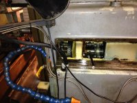

07 Right Side with Neutral Lock.jpg 08 Close up of Neutral Lock.jpg

The neutral lock is installed through the opening behind the spindle access cover on the right side of the mill. It goes on the splined shaft under the spindle shaft in the rear half of the column, in between the gear and the dividing wall. Notice that although the lower shaft is spinning, the splined shaft that the neutral lock is on is not moving.
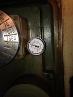

06 Interlock Pressure Gauge.jpg

With the neutral lock in place, it was safe to install a 60 psi gauge in the spindle delay and interlock pressure port. This gives much better resolution and accuracy than a 300 psi gauge for the low pressure adjustment that is required. My interlock pressure was only 7.5 psi.
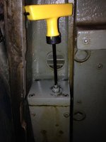

09 Interlock Adjustment.jpg

The interlock pressure adjustment is the set screw and lock nut on the cap that was removed so many times to get the constant pressure right. This is a much nicer adjustment method than using shims.

Adjusting this was easy, except that it didn't want to be in the range between 25 and 35 psi. Below was ok; above was ok; in the range was not happening. I finally left my pressure at about 37 psi.

After removing the neutral lock and pressure gauge and replacing the spindle access cover (oil flies everywhere when the gears driving the spindle are moving), all speeds come on within 5 seconds or so. :smoking:

11 Minor Oil Spill.jpg

Only a little oil splashed out for the ten or so minutes I had the neutral lock was installed. The gears in the upper column weren't spinning, so very little was flung out the opening.


One more post to follow with a few pictures of the neutral lock.
 
Neutral lock pictures

13 Neutral Lock.jpg 12 Neutral Lock.jpg 14 Neutral Lock.jpg

This is the neutral lock half collar used as noted above. And the 0.195" thick adjustment shim that wasn't quite enough. The dimensions for the collar are on page 13 of SM-66.

I made mine from a piece of 3" bar, turned down on the outside, drilled and bored on the inside, drilled and tapped for the handle, and cut in half using the 307 mill, because the 25 rpm spindle speed would usually come on even with the pressure settings all verschmeckled.
 
Thanks for posting. I went through much of the same with the spacers and such to get my machine operational. Mine is a vertical machine. I think the control pressure stays at 30 PSI I will go look again. I have not checked the spindle clutch pressure. I notice that even when adjusting the engagement delay it still is a little sluggish to come up to speed. Again Nice post and very nicely laid out. You have answered some of my questions. Tim


Back
Top