8D-132
Cast Iron
- Joined
- Mar 4, 2004
- Location
- Grants Pass, OR.USA
Hello,
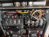
I am in need of some help figuring out why my Cleerman drill will not energize the motor starter coils. It ran when I bought it and when we moved it we had to remove the electrical box from the drill.
To which my helper made a sketch of how it was wired. That has been a few years ago and now I am in process of getting it going and following the diagram that has slightly faded over time and is giving me issues. the table works but the drill does not. This is a 220 system and I did check the motor. Everything is wired for 220, the coils are 220-208. It has 3 wire two contactor switches in the switch compartment and I have continuity to and from. They are the red wire far left and yellow far right and the black power in the front far left. The table controls work great. If I manually engage the contactors (and I don't like doing that) the motor runs smooth and reverses like it should.
I am using a 40HP phase converter and it has worked well for everything else that has reversing capability. I am reading 205 on the center leg going to the L1 leg and 120 on L2 and L3.
I wired something wrong, but what? I am missing something?


