What's new
What's new

New to us Pacemaker lathe; raised 14" x 126" and questions on steady tests

inwoodcutter

Cast Iron
Joined
Mar 10, 2005
Location
Tell City, Indiana
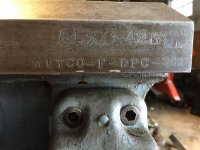
My brother and I recently won at auction a "Raised" 14" x 126" American Pacemaker. We already had a 16 x 54 and like operating Pacemakers. At first we thought the online auction listing was wrong and this was actually a 22" machine. It swings 24 1/2" over the ways but all the components are built "light" (and I use the term loosely as nothing on a Pacemaker is light) as on a 14" machine rather than the overbuilt style on a true 22" machine. What it means is a lathe that is about 5,000 lbs lighter than one built for that size swing. I'm figuring this weighs just shy of 7,000 lbs. It's great for us as we'll only really need it for occasional light use. This one was built in '55 and has very little wear. It's an extremely tight machine.

My first question is what are the limits of a raised machine vs. one built for that size? Is there a noticeable cut difference when having the cross slide all the way out to make a cut? Will I need to have some additional compensation for large work in this to account for it flexing more?

Second and see the pictures below, I want to make a steady for both this and the 16" machine that have a range up to the size that just rides over the cross slide. What should I design into the steady for something that size? I drew up something in CAD and printed it full scale, glued to plywood and cut out just to see how it looks, verify clearences. The design is very similar to the original in features and we'll likely have them burned out of thick plate.

Thanks,

Dan
 

Attachments

  • 20161115_212330.jpg
    20161115_212330.jpg
    93.7 KB · Views: 590
  • 20161206_200302.jpg
    20161206_200302.jpg
    87.3 KB · Views: 383
  • 20161206_200321.jpg
    20161206_200321.jpg
    98 KB · Views: 338
My Bulletin 16 says 3 and 6" raises were standard options

Since the non raised 14 was really a 16 1/2, the 3" gets you 22 1/2

Its a 14" lathe, this particular one can swing larger, but that in no way makes it heavy duty like the 20 heavy duty - which was near 10,000 out the door with 48" centers

Your '55 has hard outer vee ways bolted on
 
Are you sure it's a 1955? It looks exactly like my 1941. For the steady, can't you just order one from eBay and shim it like they did the tool post?
 
on the tail stock end there should be a number stamped in the bedway that should give you the year of the machine. how many speeds is it?
 
on the tail stock end there should be a number stamped in the bedway that should give you the year of the machine. how many speeds is it?


And that serial is on the VERTICAL front flat of the front way - like the thumbnail from '42 - which DOES NOT have bolt on outer hard vee ways - you are looking at 100% cast iron
 

Attachments

  • ATW Serial Location.jpg
    ATW Serial Location.jpg
    94.1 KB · Views: 183
14 X 30 in my Bulletin 16 (May '55) was 5000 net. Extra two feet of bed was 325. 126 take away 30 = 4 sets of two feet of bed or 1300 lbs. Weights published do not include motor or TA,

There is no published adder for the raised swings
 
Are you sure it's a 1955? It looks exactly like my 1941. For the steady, can't you just order one from eBay and shim it like they did the tool post?

on the tail stock end there should be a number stamped in the bedway that should give you the year of the machine. how many speeds is it?

I'm sure it's a '55. The last two of the serial number indicate the year, correct? This one is an 18 speed. Top speed is 1000 rpm. If you look at the picture of the mock up of a large steady you can see the small raised steady that came with it. What I'm after is a large capacity steady for this machine. eBay had no such thing. American didn't offer (at least as far as bulliten 16 is concerned) a steady the size I'm after.

14 X 30 in my Bulletin 16 (May '55) was 5000 net. Extra two feet of bed was 325. 126 take away 30 = 4 sets of two feet of bed or 1300 lbs

That's exactly how I figured the weight. 6300 plus some for the raise and motor. So just shy of 7K.

Has anyone made their own steady? I'd like some feedback on that.
 
Has anyone made their own steady? I'd like some feedback on that.

Never built one myself, but I've used some pretty big homemade ones, largest could hold about 3' dia. It was fabricated to simulate a casting, two heavy rings burned from plate, round on the inside, but hexagonal on the outside, with ribs between them spaced every 6"-8", making it about 6" wide. It was two pieces that bolted together, the top lifting off rather than hinging back, and it used two adjustable arms with jack screws on the bottom and two on the top, for four total 90* apart. The end of the arms were forked to hold a large ball bearing on a pin.
I recommend making yours two pieces rather than having a hinge. It's simpler to make, stronger, easier to access with large shafts, and it's much easier to lower the top half on with a crane than control all that weight swinging down on a hinge.
 
Another route you could go, is aluminum. I've seen a few cast out of it that were nice. I've gotten some quotes on stuff about that size and it wasn't too bad. That would be the route I'd go.
 
The shop made one for my old L&S isn't going to win beauty pageants, but it is very effective. Burned out of 3/4" plate left as burned and stick welded together. Wonderful to have a steady with a 16" hole. Seen here holding a printing press cylinder that had the trunnion broken off. I shrunk a bronze ring onto the end of the cylinder for the steady fingers to run on.
 

Attachments

  • lathe.jpg
    lathe.jpg
    92.6 KB · Views: 259
That's the reason we got it. It has a hydraulic ram in it right now. Getting the threaded end repaired.

Aside from the effort to get the steady on and off is weight beneficial to the steady? Would a heavier steady be a better one for any reason? The large steady planned will have a 17" thru bore on it.

Dan
 
Just rigidity and durability. Cast iron has no tensile strength, so parts like the tops of steadies made out of iron are severely overbuilt. I have seen the hinges snapped clean off a steady top because the guy pitched it back and didn't catch it before it went back and hit the stop, full force. Same for getting a chip under a roller or such.
 
You need to decide weather you want rollers or brass pads in your steady.

Regards Tyrone.

I you decide to use rollers look at cam followers. They are nice and wide, as well as the outer race edges are radiused well. I personally prefer cast iron tips over brass. Never did like how brass grows so much when it get hot. And iron on steel bearings were used for a hundred years with good results.
 
You need to decide weather you want rollers or brass pads in your steady.

Regards Tyrone.

If I was designing something from the ground up, i would make sure my options were left open on that matter. In fact, every steady I've ever had to use more than a couple of times wound up modified so I would at least have my choice of pads, if not also the option of rollers.
Rollers make things simple and work very well much of the time. There are however, times that they just won't do what is needed. Bronze pads, or, in the right situation even delrin pads, are the answer at times, but a plain bearing needs constant lube and attention, so they are not always practical.
Bottom line is I like for the ends of the supports to be easily changed to suite the need at hand.
 
Downside to rollers is that they don't handle really heavy parts well. Have smashed several of them when at the chrome shop with huge solid hydraulic rods. Generally found the bronze pads to do less damage on heavy items, provided they were properly lubed. We used copper based anti-seize and loads of way oil. If you can't mar the work at all, need to make up a cathead or shrink on a sacrificial ring. Ring can be steel for bronze fingers or rollers. Bronze for iron fingers or rollers.


Back
Top